
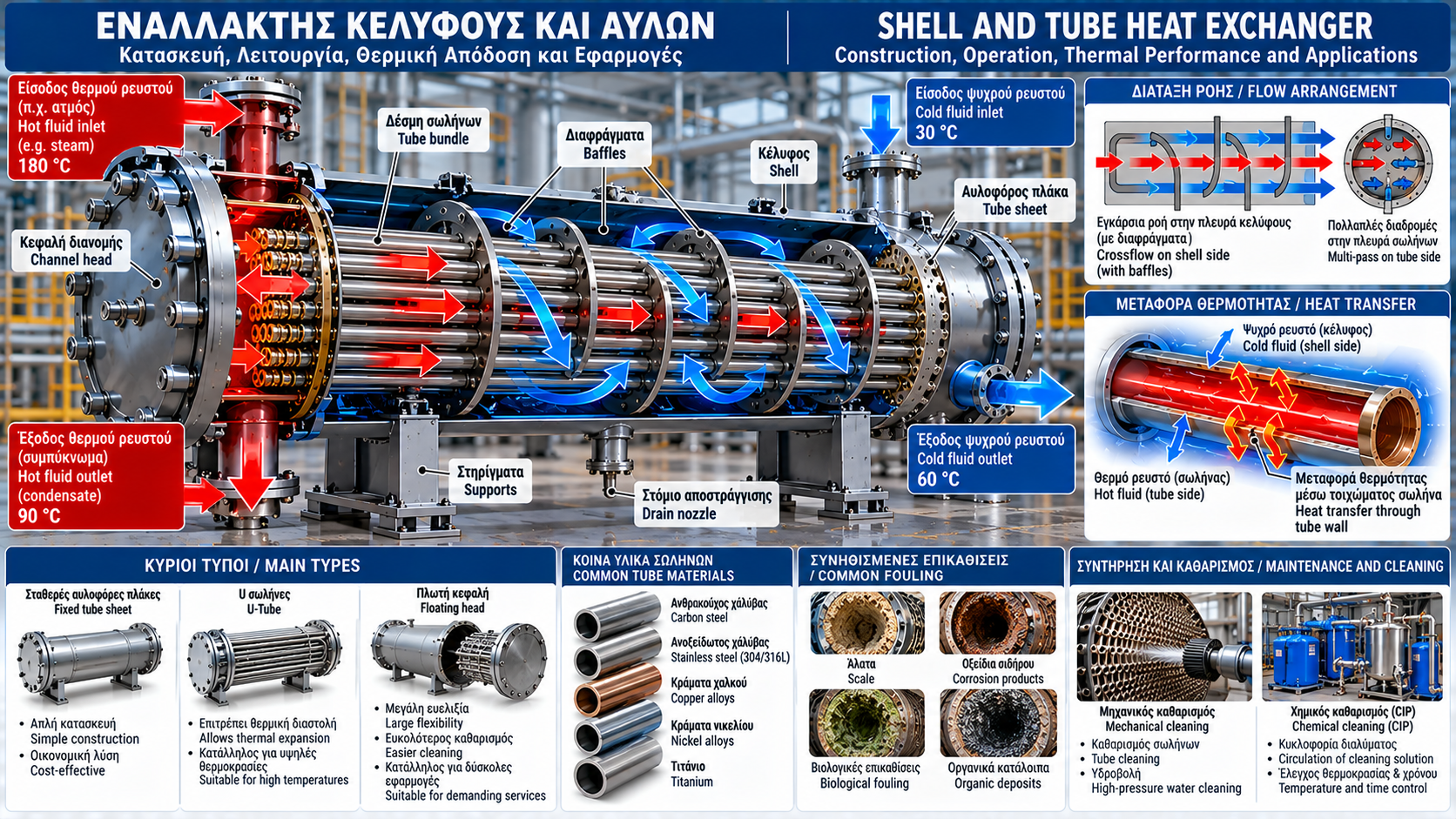
# Shell and Tube Heat Exchangers: Construction, Operation, Thermal Performance and Industrial Applications
## Introduction
Shell-and-tube heat exchangers are essential heat transfer equipment in industrial facilities. They are widely used in steam systems, hot-water generation, chemical processing, power plants and applications requiring reliable performance under significant thermal and mechanical loads.
Their construction supports different flow arrangements, materials and maintenance strategies. Thermal performance depends not only on exchanger size but also on hydraulic design, operating temperatures and the condition of heat transfer surfaces.
## 1. What Is a Shell-and-Tube Heat Exchanger?
A shell-and-tube exchanger consists of a cylindrical shell surrounding a bundle of tubes.
One fluid flows inside the tubes, known as the tube side, while another flows through the space between the tubes and shell, known as the shell side.
Heat transfers through the tube walls. In a properly functioning indirect-contact exchanger, the fluids remain separated.
## 2. Main Construction Components
The main components include:
• Shell: the outer pressure-containing vessel.
• Tubes: the principal heat transfer surfaces.
• Tube sheets: components securing and sealing tube ends.
• Baffles: devices directing shell-side flow and supporting the tube bundle.
• Channel heads: components distributing tube-side flow.
• Inlet and outlet nozzles: process connections.
• Supports, gaskets and joints: components maintaining mechanical integrity and tightness.
## 3. Operating Principle
The hotter fluid transfers heat to the tube wall.
Energy moves by convection from the hot fluid, conduction through the metal and convection to the colder fluid.
Heat transfer duty depends on flow rates, fluid properties, surface area, temperature difference and tube cleanliness.
Some services involve a phase change, such as steam condensing while heating water.
## 4. Tube Side and Shell Side
Assigning fluids to the tube or shell side is a design decision.
Relevant factors include:
• Pressure and temperature.
• Corrosiveness and material compatibility.
• Viscosity and fouling potential.
• Cleaning access.
• Allowable pressure drop.
• Leakage consequences and safety requirements.
There is no universal rule requiring the hot fluid to flow on a particular side.
## 5. Role of Baffles
Baffles guide shell-side fluid flow and mechanically support the tubes.
Many baffle arrangements create crossflow over the tube bundle, improving heat transfer.
However, baffles also contribute to pressure drop.
Their spacing and geometry are selected to balance thermal performance, hydraulic losses and vibration control.
## 6. Single-Pass and Multi-Pass Designs
In a single-pass tube-side arrangement, fluid crosses the tube bundle once.
In multi-pass arrangements, the flow is redirected through additional tube groups.
Increasing the number of passes may increase velocity and convective heat transfer, but it also increases pressure drop.
Both effects must be considered during design.
## 7. Main Mechanical Designs
Common designs include:
• Fixed tube-sheet exchangers.
• U-tube exchangers.
• Floating-head exchangers.
Fixed tube-sheet designs offer a relatively straightforward construction.
U-tube designs accommodate differential thermal expansion, although cleaning the inside of U-bends can be challenging.
Floating-head designs provide additional flexibility for thermal expansion and certain maintenance operations.
## 8. Thermal Expansion
The shell and tubes may operate at different temperatures.
This produces differential thermal expansion.
In certain configurations, differential expansion can generate substantial mechanical stress.
Suitable solutions include U-tubes, floating heads or other approved design arrangements.
## 9. Construction Materials
Common materials include:
• Carbon steel.
• Stainless steel.
• Copper alloys.
• Nickel alloys.
• Titanium for selected services.
Material selection depends on fluid chemistry, pressure, temperature, corrosion risk and applicable construction requirements.
## 10. Thermal Duty Calculation
For a single-phase fluid with approximately constant heat capacity:
Q̇ = ṁ × cp × ΔT
Where:
Q̇ = thermal duty (kW).
ṁ = mass flow rate (kg/s).
cp = specific heat capacity [kJ/(kg·K)].
ΔT = fluid temperature change (K).
Under steady operating conditions, heat released by the hot stream approximately equals heat absorbed by the cold stream when environmental losses are small.
## 11. Practical Example
Consider a water circuit operating at:
Flow rate: 15 m³/h.
Inlet temperature: 85 °C.
Outlet temperature: 65 °C.
Using approximate water density of 1,000 kg/m³ and cp = 4.18 kJ/(kg·K):
ṁ ≈ 15,000 / 3,600 = 4.17 kg/s.
Q̇ ≈ 4.17 × 4.18 × 20 = 348 kW.
The circuit therefore releases approximately 348 kW of thermal power.
For greater accuracy, use actual water properties at the operating temperatures.
## 12. Overall Heat Transfer Coefficient
A common design equation is:
Q̇ = U × A × ΔTlm × F
Where:
U = overall heat transfer coefficient.
A = heat transfer area.
ΔTlm = logarithmic mean temperature difference.
F = correction factor for the actual flow arrangement when required.
The coefficient U depends on convective coefficients, tube-wall thermal resistance and fouling.
## 13. Logarithmic Mean Temperature Difference
The logarithmic mean temperature difference, or LMTD, is used because the temperature difference between the fluids varies along the exchanger.
For an appropriate simple flow arrangement:
ΔTlm = (ΔT₁ − ΔT₂) / ln(ΔT₁ / ΔT₂)
The equation applies when the terminal temperature differences are positive and the thermal model is appropriate.
Multi-pass exchangers frequently require an LMTD correction factor or a more detailed calculation method.
## 14. Pressure Drop
Pressure drop depends on:
• Flow rate.
• Tube diameter and length.
• Number of passes.
• Baffle geometry.
• Fluid viscosity.
• Fouling deposits.
Excessive pressure drop increases pumping requirements and may restrict flow.
Tube-side and shell-side pressure drops should be evaluated separately.
## 15. Tube Fouling
Deposits reduce effective heat transfer.
Common causes include:
• Hardness scale.
• Iron oxides.
• Suspended solids.
• Biological deposits.
• Process residues.
Fouling adds thermal resistance and can reduce the available flow cross-section.
## 16. Corrosion and Tube Failure
Corrosion may cause wall thinning, leakage and tube failure.
Possible mechanisms include:
• General corrosion.
• Localized pitting.
• Crevice corrosion.
• Flow-related corrosion under suitable conditions.
• Stress corrosion cracking in susceptible materials and environments.
Reliable assessment requires inspection and suitable nondestructive testing methods.
## 17. Tube Vibration
Flow velocity and baffle geometry can produce flow-induced tube vibration.
Excessive vibration may cause wear at support points, fatigue and eventual leakage.
Correct mechanical design and flow control are important.
Unusual noise or vibration should be investigated.
## 18. Steam Heating Applications
In a steam-to-water exchanger, steam may condense on one side, releasing latent heat.
Condensate removal must be effective.
Problems in the condensate line or steam trap may cause condensate accumulation, reduced heat transfer and water hammer.
Control-system selection must also account for low-load operating conditions.
## 19. Operating Measurements
Useful measurements include:
• Tube-side inlet and outlet temperatures.
• Shell-side inlet and outlet temperatures.
• Flow rates of both streams.
• Inlet and outlet pressures on each side.
• Differential pressure.
• Valve and filter condition.
These data support thermal duty calculations and hydraulic performance assessment.
## 20. Mechanical and Chemical Cleaning
Cleaning methods include:
• Mechanical cleaning of accessible tubes.
• High-pressure water cleaning using approved equipment and procedures.
• Chemical cleaning or CIP where permitted.
• Specialized cleaning methods selected for the deposit type.
The appropriate method depends on geometry, tube material and fouling characteristics.
Not all designs provide equivalent mechanical cleaning access.
## 21. Inspection and Testing
Scheduled inspections may include:
• Visual inspection.
• Leak testing.
• Wall-thickness measurement.
• Eddy-current or other suitable nondestructive testing.
• Tube-sheet and joint inspection.
• Corrosion and wear assessment.
Pressure testing and equipment isolation must be performed by qualified personnel using approved procedures.
## 22. Selection Criteria
Correct selection requires:
1. Design thermal duty.
2. Inlet and outlet temperatures.
3. Fluid flow rates and properties.
4. Design pressures and temperatures.
5. Allowable pressure drops.
6. Construction materials.
7. Fouling assessment.
8. Cleaning requirements.
9. Differential thermal expansion and mechanical loads.
10. Applicable design codes and regulatory requirements.
Pressure equipment must have the technical documentation and compliance required by the applicable regulatory framework.
## 23. Conclusion
Shell-and-tube heat exchangers provide a versatile and durable solution for many industrial heat transfer applications.
Reliable operation requires suitable geometry, thermal expansion management, acceptable pressure drop and planned maintenance.
Recording real operating measurements supports early detection of fouling, leakage and declining performance.
Thermosphere.gr — Technical knowledge for industry, heating and energy efficiency.