
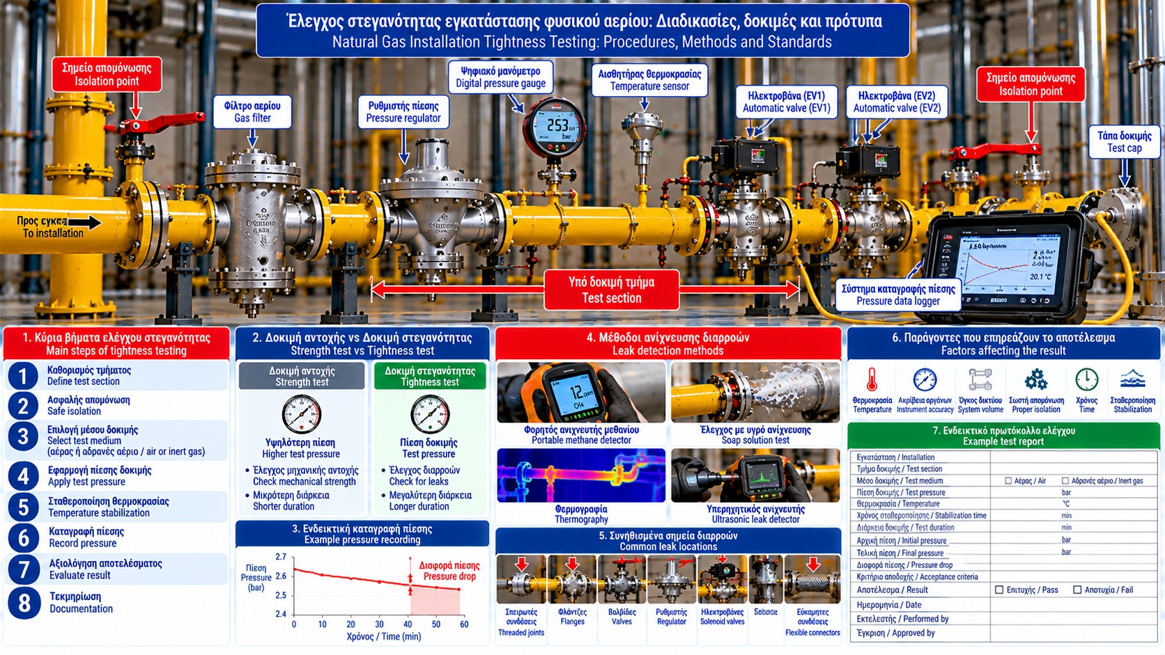
Natural Gas Installation Tightness Testing: Procedures, Methods and Standards
Tightness testing is an essential process for verifying the safety of natural gas piping systems. It is performed during construction, before initial commissioning and, where required, after repairs, modifications or during the installation’s operating life.
In industrial facilities supplying boilers, burners, furnaces and other gas consumers, tightness verification involves more than observing a pressure gauge.
Reliable testing requires an approved procedure, safe isolation, suitable instruments and documented acceptance criteria.
1. What Is Tightness Testing?
Tightness testing evaluates whether a defined section of an installation leaks beyond the limits permitted by the applicable specification.
It may cover piping, joints, flanges, isolation valves, network components, gas supply assemblies and repaired sections.
The test boundary and conditions must be clearly defined.
2. Strength Testing Versus Tightness Testing
These tests serve different purposes.
Strength testing: Assesses whether the test section can withstand the specified test pressure without unacceptable failure.
Tightness testing: Evaluates whether unacceptable leakage occurs.
A successful strength test does not automatically establish tightness.
Test sequence, pressure, duration and acceptance criteria are determined by the applicable standard and approved procedure.
3. When Is Testing Required?
Testing may be required before commissioning, after new construction, pipe replacement, joint repairs, component changes, certain maintenance activities or when leakage is suspected.
The required scope depends on the intervention and applicable regulatory requirements.
4. Why One Procedure Cannot Cover Every Installation
Gas installations vary in operating pressure, allowable pressure, pipe diameter, length, materials, system volume, installed equipment and environmental conditions.
Therefore, a single test pressure or duration should not be applied universally.
5. Defining Test Boundaries
The exact section to be tested must be identified before work begins.
This includes isolation points, connected consumers and equipment that may not be rated for the test conditions.
Regulators, instruments, pressure switches and automatic valves may have different pressure limitations from the piping.
Not all components can necessarily withstand the piping test pressure.
6. Safe Isolation
Safe isolation is a prerequisite for testing.
Depending on the installation, approved mechanical isolation and verification measures may be required.
Simply moving a valve handle to the closed position is not always sufficient proof of safe isolation.
Work must be performed by authorized personnel under approved procedures and risk controls.
7. Selecting the Test Medium
The test medium must be specified by the applicable standard and approved procedure.
Air or inert gas may be used in many applications under defined conditions.
Selection must account for cleanliness, material compatibility and safety.
Oxygen must not be used arbitrarily for natural gas piping tests.
Flammable gas must not be assumed to be an acceptable test medium without explicit procedural authorization.
8. Pressure Measurement Instruments
Suitable instruments may include digital pressure gauges, pressure transmitters, data loggers, calibrated analog gauges and temperature sensors.
Selection must consider range, resolution, accuracy and calibration status.
An instrument with an excessively broad range may not provide adequate resolution for the required test.
9. Temperature Effects
Pressure in a closed gas volume is affected by temperature.
A temperature decrease may cause a pressure drop without leakage.
Conversely, increasing temperature may conceal a small pressure loss.
Testing therefore requires suitable thermal stabilization or temperature consideration as specified by the procedure.
10. Stabilization Before Recording
Following pressurization, the system may require time to reach stable thermal and mechanical conditions.
Recording measurements too early can lead to incorrect conclusions.
Stabilization time must follow the approved procedure.
11. Pressure Monitoring Method
In suitable applications, tightness may be assessed by monitoring pressure in an isolated test section.
The general methodology involves defining the boundary, verifying isolation, applying the approved test method, allowing stabilization, recording pressure and temperature where required, assessing results and documenting the outcome.
This description is not a substitute for an approved field testing procedure.
12. Local Joint Inspection
Specific joints may require local leak inspection.
Approved detection fluids or specialized instruments may be appropriate, depending on accessibility and installation conditions.
Open flames must never be used to detect leaks.
13. Why Pressure Loss Does Not Always Prove Leakage
Pressure loss may result from actual leakage, temperature changes, incomplete isolation, instrument problems or insufficient stabilization.
These factors must be assessed before concluding that a leak exists.
Likewise, the absence of a measurable pressure drop does not universally prove zero leakage.
14. Acceptance Criteria
Test results must be evaluated against predefined criteria.
These may include permitted pressure variation, observation duration, temperature correction and other requirements.
Values depend on the applicable standard and approved procedure.
No single pressure, duration or pressure-drop limit is universally valid for all natural gas installations.
15. Testing After Repairs
After repair or replacement, the required retesting scope must be determined.
A successful local inspection does not necessarily replace other required tests.
Return to service requires completion of the applicable checks and approvals.
16. Piping Tightness Testing Versus Valve Proving
These are separate activities.
Piping tightness testing: Assesses external tightness of the defined installation section.
Valve proving: Assesses automatic shut-off valve tightness using the specified proving system.
Successful valve proving does not certify the overall piping network against external leakage.
17. Common Testing Errors
Typical errors include unsuitable instruments, missing calibration records, ignoring temperature effects, poorly defined test boundaries, including pressure-sensitive components, inadequate isolation, arbitrary test duration and incomplete documentation.
Avoiding these errors is essential for reliable results.
18. Test Documentation
A test record may include:
Field | Information |
Installation | Site and network identification |
Test section | Boundaries and reference drawing |
Procedure | Applicable standard and approved method |
Test medium | Specified medium |
Instruments | Identification and calibration |
Conditions | Pressure and temperature as required |
Timing | Start, end and stabilization period |
Measurements | Recorded readings |
Acceptance criteria | Applicable limits |
Result | Pass or fail |
Personnel | Test performer and approver |
Remarks | Findings and corrective actions |
The exact documentation format depends on the installation and applicable requirements.
19. What Happens After a Failed Test?
A failed test must not be addressed by arbitrarily increasing pressure or repeating the test without investigation.
The procedure, measurement conditions and possible leakage must be assessed.
Confirmed defects require appropriate repair and the specified retest.
The affected section must remain out of service until the required actions have been completed.
20. Technical Standards
Relevant references include:
EN 15001-1: Design, construction, inspection and testing of gas installations within its scope.
EN 15001-2: Operation and maintenance requirements for applicable installations.
EN 1775: Gas pipework for buildings within its scope.
EN 1643: Valve proving systems.
EN 60079-29-2: Selection, installation, use and maintenance of flammable gas detectors.
Applicability depends on installation pressure, equipment type and national requirements.
Conclusion
Natural gas tightness testing is a structured engineering process, not merely an observation of pressure variation.
Its reliability depends on properly defined boundaries, safe isolation, suitable instrumentation, temperature assessment and predetermined acceptance criteria.
Complete documentation is an essential part of demonstrating that the required testing has been performed before an installation is placed or returned into service.