
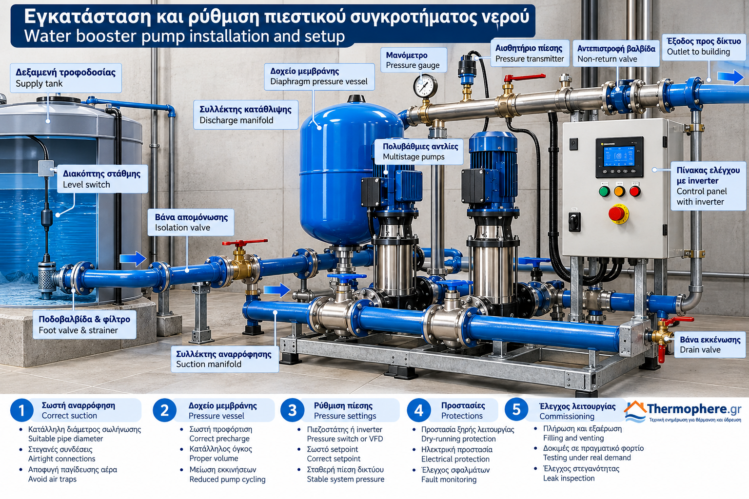
Water Booster Pump Installation and Setup: Complete Technical Guide
Correct installation and configuration are essential for the reliable operation of a water booster pump system.
Even a properly selected booster set may suffer from unstable pressure, excessive pump cycling, cavitation, vibration or premature equipment failure when its hydraulic connections and control parameters are incorrect.
Installing a booster system involves more than positioning the pumps and connecting the pipework. It requires verification of the water supply, proper suction and discharge arrangements, pressure vessel configuration, electrical protection and commissioning under representative demand conditions.
This guide explains the main technical principles involved in installing and setting up fixed-speed and variable-speed water booster systems.
1. Preliminary checks before installation
Before installing the booster set, the hydraulic requirements of the water distribution system must be established.
Essential design information includes:
Required design flow rate in m³/h.
Required total dynamic head in metres.
Minimum and maximum available inlet pressure.
Elevation difference to the most demanding outlets.
Pipework pressure losses.
Maximum allowable pressure of the connected components.
Expected variations in water demand.
Required operational redundancy.
The manufacturer’s pump performance curves, electrical supply requirements and operating limits must also be checked.
Suction conditions are particularly important.
A pump may satisfy the required flow and head at its nominal duty point but still operate poorly if the available inlet pressure is inadequate.
2. Selecting the installation location
The booster set should be installed in a location that provides safe operating conditions and sufficient access for inspection and maintenance.
The installation area should provide:
A stable and level foundation.
Adequate ventilation for motors and electronic equipment.
Protection against flooding, freezing and excessive moisture.
Access to pumps, valves, sensors and control panels.
Suitable drainage where necessary.
Appropriate noise and vibration control.
In apartment buildings and commercial properties, the proximity of the equipment to occupied spaces should be considered.
The foundation must be capable of supporting the equipment weight and operating loads.
Anti-vibration mounts and flexible connectors may be used where specified by the engineering design and manufacturer.
They do not replace correct pipe support and alignment.
3. Correct suction pipe installation
The suction arrangement is one of the most critical elements of a booster pump installation.
The suction pipe must deliver sufficient water to the pump while limiting pressure losses and preventing air ingress.
Main suction design principles
The suction line should:
Have a suitable diameter for the required flow.
Be as short and hydraulically smooth as practical.
Avoid unnecessary elbows, restrictions and high-resistance fittings.
Have airtight connections.
Avoid configurations that trap air.
Follow the manufacturer’s requirements for straight pipe lengths and connections.
Where the pump is positioned above the water level, the system’s priming and suction-lift capabilities require particular attention.
If a foot valve or other water-retaining device is used, it must be correctly selected and its additional pressure loss must be considered.
Suction from a storage tank
A properly designed supply tank can provide predictable inlet conditions.
Important considerations include:
Minimum water level.
Suction outlet positioning.
Prevention of vortex formation.
Protection against air and debris entering the pump.
Adequate tank replenishment capacity.
For drinking water applications, the tank and connected materials must be suitable for potable water service.
Direct connection to a public water main
Direct pump suction from a public water main is not automatically permitted.
The relevant water utility requirements, local regulations and backflow prevention provisions must be checked.
Where required, an intermediate break tank must be provided.
4. Suction conditions and NPSH
Insufficient inlet pressure may cause pump cavitation.
Cavitation occurs when local liquid pressure falls sufficiently for vapour bubbles to form.
When these bubbles collapse in higher-pressure regions, they can cause noise, vibration, performance loss and damage to hydraulic components.
The available Net Positive Suction Head, NPSHa, must be assessed against the pump’s required NPSH, NPSHr.
An appropriate engineering margin must be maintained in accordance with the manufacturer’s guidance and the operating conditions.
5. Discharge pipework installation
The discharge pipe transfers water from the booster set to the distribution network.
Depending on the installation, the discharge arrangement may include:
Isolation valves.
Non-return valves.
Pressure gauges.
Pressure transmitters.
A diaphragm pressure vessel.
Overpressure protection where required.
Suitable drainage and venting points.
Non-return valves prevent unwanted reverse flow when a pump stops.
Multi-pump booster systems commonly include an appropriate non-return arrangement for each pump, according to the manufacturer’s design.
Pipework must be independently supported to prevent excessive mechanical loads from being transferred to pump connections.
6. The role of the diaphragm pressure vessel
A diaphragm pressure vessel is an important component for maintaining stable booster operation.
It contains a pressurised gas volume separated from the water by a flexible diaphragm or membrane.
When the pump operates, water enters the vessel and compresses the gas.
When demand is low, the vessel can supply a limited amount of water without requiring the pump to restart immediately.
This reduces unnecessary pump cycling and associated mechanical stress.
What is vessel precharge pressure?
Precharge is the gas pressure inside the vessel when the water side is depressurised and drained.
It must be measured with the vessel hydraulically isolated and the water pressure released.
Reading the system pressure gauge while the vessel remains pressurised does not provide a valid measurement of the gas precharge.
Example for a conventional booster
Consider a conventional system with:
Cut-in pressure: 2.0 bar.
Cut-out pressure: 3.5 bar.
For certain conventional pressure vessel arrangements, the precharge may be set approximately 0.2 bar below the cut-in pressure.
In this example:
Precharge ≈ 1.8 bar
This is an illustrative value, not a universal setting.
The correct precharge depends on the vessel type, installation arrangement, control strategy and manufacturer instructions.
Variable-speed booster systems may require substantially different precharge settings.
7. Pressure switch adjustment
A pressure switch controls pump starting and stopping according to measured system pressure.
The two main settings are:
Cut-in pressure: The pressure at which the pump starts.
Cut-out pressure: The pressure at which the pump stops.
The difference between these values is known as the pressure differential.
For example:
Cut-in: 2.0 bar.
Cut-out: 3.5 bar.
Differential: 1.5 bar.
Why does the pressure differential matter?
An excessively small differential may cause frequent pump cycling, particularly when the pressure vessel has limited usable water capacity.
An excessively large differential may create noticeable pressure variations at the outlets.
Correct settings depend on:
Minimum required network pressure.
Maximum allowable system pressure.
Pressure vessel capacity and precharge.
Pump performance.
Allowable motor starting frequency.
Important safety note
Pressure switches do not all use the same adjustment mechanism.
Some mechanical models provide separate adjustments for the main pressure setting and the differential. Others use different arrangements.
The manufacturer’s instructions for the exact model must be followed.
Before accessing internal electrical components, the supply must be isolated and absence of voltage verified by qualified personnel.
8. Variable-speed booster pump configuration
Variable-speed booster systems use a VFD to regulate pump rotational speed and maintain a selected pressure.
The principal control parameter is the pressure setpoint.
A pressure transmitter continuously measures actual system pressure, and the controller adjusts motor speed to compensate for changing demand.
Common control parameters
Depending on the manufacturer, configuration may include:
Pressure setpoint.
Minimum and maximum operating frequency.
Acceleration and deceleration times.
Low-pressure limits.
Sleep and wake-up conditions during low demand.
Dry-running protection.
Fault recovery and restart conditions.
Pump alternation and staging.
Selecting the pressure setpoint
The setpoint must provide adequate pressure at the most demanding outlets during the expected design flow.
Elevation differences, pipe losses and the pressure transmitter location must be considered.
An unnecessarily high setpoint may increase energy consumption and impose additional stress on the distribution system.
A setpoint that is too low may result in inadequate pressure at elevated or remote outlets.
Why sensor location matters
The pressure transmitter must be installed at the location specified by the manufacturer and the control design.
Pressure measured at the booster discharge manifold is not necessarily equal to the pressure at the hydraulically most remote outlet.
Some systems use remote pressure sensing or pressure compensation strategies to address distribution losses.
9. Dry-running protection
Operating a pump without sufficient water supply can cause severe equipment damage.
Insufficient water may result in inadequate cooling or lubrication, overheating and damage to mechanical seals.
Dry-running protection may be provided through:
Tank level switches.
Electronic level sensors.
Low-pressure switches on the suction side.
Suitable flow sensors.
Dedicated monitoring functions in the pump controller.
The appropriate method depends on the water source and equipment configuration.
Dry-running protection should not be bypassed to maintain temporary operation.
10. Electrical installation and protection
Electrical installation must be carried out by appropriately qualified personnel in accordance with applicable regulations.
Important checks include:
Supply voltage and frequency.
Rated motor current.
Overcurrent and short-circuit protection.
Protective earthing.
Appropriate protection against electric shock.
Compatibility of protective devices with the VFD.
Correct motor rotation where applicable.
Protection of wiring against moisture and mechanical damage.
Variable frequency drives may impose specific requirements relating to electromagnetic compatibility, cable shielding, grounding and residual-current protective devices.
Manufacturer instructions must be followed.
11. Priming, venting and initial commissioning
Before the first start, the hydraulic system must be properly filled and free from trapped air that could affect operation.
The exact priming procedure depends on the pump design and suction arrangement.
A typical commissioning process includes:
Inspecting mechanical supports and connections.
Confirming the correct valve positions.
Filling and venting the system according to the manual.
Verifying the available water supply.
Checking the electrical installation.
Confirming control parameters.
Performing a controlled initial start.
Monitoring pressure, flow, noise and vibration.
Checking for leaks.
Testing performance under different demand conditions.
The pump must not be operated without the required priming or outside the manufacturer’s permitted operating limits.
12. Testing under representative demand conditions
Successful initial starting does not mean commissioning is complete.
The booster system should be tested under different water demand conditions.
Low demand
At low demand, the system should maintain stable operation without excessive cycling.
For fixed-speed systems, the number of pump starts should be assessed.
For VFD systems, minimum-flow behaviour and pressure control stability should be checked.
Medium demand
The system should maintain the required pressure under normal operating conditions.
Maximum design demand
The booster set must deliver the design flow without unacceptable pressure loss, motor overload or operation outside permitted limits.
No demand
The system should stop or enter its intended standby mode correctly.
Pressure stability and non-return valve operation should also be verified.
13. Common installation mistakes
Undersized suction piping
Excessive suction losses may reduce available inlet pressure and increase cavitation risk.
Trapped air
Air pockets can cause noise, unstable operation and reduced hydraulic performance.
Incorrect vessel precharge
Incorrect precharge may reduce usable vessel capacity and increase pump cycling.
Excessive operating pressure
An unnecessarily high pressure setpoint may increase energy consumption and stress pipework and fittings.
Missing dry-running protection
The pump may suffer severe damage when the water supply is interrupted.
Poor pipe support
Improper support may transfer mechanical loads to pump connections and increase vibration.
Incorrect VFD parameters
Poor control settings may cause pressure oscillations, unnecessary starting or operation outside the appropriate range.
14. Maintenance after commissioning
Regular maintenance helps preserve system efficiency and reliability.
Depending on the manufacturer’s recommendations and the operating environment, inspections may include:
Leak checks.
Noise and vibration monitoring.
Electrical connection inspection by qualified personnel.
Pressure vessel precharge checks using the correct isolation procedure.
Sensor and instrument verification.
Testing of protective functions.
Filter cleaning where applicable.
Review of controller fault logs.
Confirmation that operating pressures remain within the specified limits.
Maintenance intervals should follow the manufacturer’s instructions and actual operating conditions.
Conclusion
Correct water booster pump installation and configuration are essential for stable pressure, reliable operation and reduced energy and mechanical stress.
Hydraulic connections, suction conditions, pressure vessel precharge, pressure switch or VFD settings and protective devices must be considered as parts of one integrated system.
A properly installed booster set is not simply a pump that starts and stops. It is a controlled hydraulic system designed to respond safely and efficiently to the actual demands of the water distribution network.
This article provides general technical information and does not replace project-specific engineering, manufacturer instructions or work by qualified installation professionals.
Thermosphere.gr — Technical knowledge for heating, water supply and modern plumbing systems.