
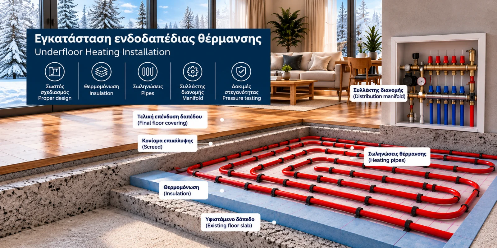
Underfloor Heating Installation: Pipes, Insulation and Proper Design
Hydronic underfloor heating can provide comfortable and efficient space heating, particularly when combined with low-temperature heat sources such as heat pumps.
However, system performance depends heavily on correct design and installation quality.
Unlike conventional radiators, underfloor heating pipes are embedded within the floor construction. Once the floor is completed, access to the pipes is limited.
For this reason, material selection, pipe spacing, thermal insulation and pressure testing require careful attention.
This guide explains the main stages involved in installing a hydronic underfloor heating system.
1. Heat-Loss Calculations Before Installation
Every installation should begin with a room-by-room heat-loss assessment.
The calculation considers:
Room dimensions and volume.
Insulation levels of walls, roofs and floors.
Window and glazing characteristics.
Outdoor design temperatures.
Required indoor temperatures.
Ventilation heat losses.
The results determine the heating output required for each room, the circuit layout, water flow rates and design supply temperatures.
Without accurate calculations, the system may provide insufficient heating or uneven room temperatures.
2. Preparing the Floor Structure
Before installation, the existing floor structure must be inspected.
The substrate should be clean, stable and sufficiently level according to the selected system's requirements.
A conventional installation may include:
Structural slab or existing substrate.
Thermal insulation.
Heating pipes.
Heated screed or another suitable heat-distribution layer.
Finished floor covering.
The total construction depth depends on the installation method and materials.
Low-profile systems may be considered for renovation projects where available floor height is limited.
3. Installing Thermal Insulation
Thermal insulation is a critical component of underfloor heating.
Its purpose is to reduce downward heat losses and improve the proportion of useful heat transferred into the occupied space.
Insulation panels must provide suitable thermal resistance and compressive strength for the expected loads.
The required insulation thickness depends on the floor's location and the thermal conditions below it.
Floors above heated rooms, unheated spaces and the ground may require different insulation specifications.
Perimeter edge insulation strips are commonly installed to accommodate screed movement and separate the heated layer from adjacent structural elements.
4. Selecting Underfloor Heating Pipes
Heating pipes distribute warm water throughout the floor.
Common materials include:
Cross-linked polyethylene (PEX).
Polyethylene of raised temperature resistance (PE-RT).
Suitable multilayer composite pipes.
Pipes must be approved for the intended heating application and meet the relevant temperature, pressure and oxygen-diffusion requirements.
Outside diameters of 16 or 17 mm are commonly used, although final selection depends on the system design and manufacturer specifications.
The minimum permitted bending radius must always be respected during installation.
5. Pipe Layout and Spacing
Pipe layout influences both heat distribution and hydraulic performance.
Two common arrangements are:
Spiral layout: Supply and return sections run close together, helping create a more uniform floor temperature.
Serpentine layout: The pipe follows successive parallel runs and may be suitable for specific room geometries or areas with increased heat losses.
Typical design spacings may include 100, 150 or 200 mm, but these are examples rather than universal requirements.
Correct spacing depends on heating demand, water temperature, floor covering and the performance characteristics of the selected system.
Areas near large glazed surfaces may require closer spacing when supported by the heat-loss calculation.
6. Circuit Length and Hydraulic Design
Each heating circuit connects to the supply and return manifold.
The allowable circuit length depends on:
Pipe diameter and material.
Required water flow.
Pressure losses.
Available pump head.
Room heating demand.
There is no single maximum circuit length suitable for every installation.
The designer must ensure that circuits deliver the required heat output without excessive hydraulic resistance.
7. Installing the Distribution Manifold
The manifold distributes water to the individual heating circuits.
Depending on the equipment, it may include flow regulators, isolation valves, filling connections, air vents and provisions for actuators.
The manifold should be installed in an accessible location to allow inspection, adjustment and maintenance.
Its location also influences pipe routing and circuit lengths.
8. Pressure and Leak Testing
Pressure testing is one of the most important installation stages.
Before the pipes are covered, the system must be tested according to the applicable standards and manufacturer instructions.
The test helps identify leaks in pipes and connections.
Test pressure and duration must be determined by the relevant technical requirements rather than selected arbitrarily.
Results should be documented in an installation test report.
9. Installing the Heated Screed
In conventional wet systems, the heating pipes are embedded in a suitable screed.
The screed distributes heat from the pipes to the finished floor surface.
Installation requirements include:
Correct screed type and thickness.
Appropriate movement joints.
Protection of heating pipes.
Specified curing and drying conditions.
Compatibility with the final floor covering.
Premature heating or incorrect drying procedures can damage the floor construction.
10. Initial Commissioning
The system must not be operated before the required curing periods and checks have been completed.
The initial heating procedure should follow the screed manufacturer's prescribed commissioning protocol.
Commissioning normally includes:
Filling and venting the circuits.
Checking system pressure.
Adjusting manifold flow rates.
Verifying supply-water temperature.
Testing thermostats and controls.
Hydraulic balancing.
Proper balancing ensures that each circuit receives its design water flow.
11. Common Installation Mistakes
Several installation errors can reduce system performance.
Insufficient insulation: Increases unwanted downward heat losses.
Incorrect pipe spacing: Can result in inadequate or uneven heat output.
Excessive circuit lengths: Increase pressure losses and complicate balancing.
Missing pressure tests: Increase the risk of discovering leaks after floor completion.
Incorrect initial heating: May damage the heated screed.
Poor hydraulic balancing: Can produce temperature differences between rooms.
12. Frequently Asked Questions
How much floor depth is required?
The required depth depends on the heating system, insulation, pipe dimensions and finished floor covering. Conventional and low-profile systems have different construction requirements.
What is the ideal pipe spacing?
There is no universal ideal spacing. It must be determined through thermal calculations and the selected system's specifications.
Are pipe joints allowed inside the floor?
Continuous pipe circuits without intermediate joints are generally preferred. Any exception must be explicitly permitted by the approved system and applicable technical requirements.
When can the heating system be switched on?
Only after the required curing period and after following the specified initial heating procedure.
Conclusion
Installing hydronic underfloor heating involves much more than placing pipes beneath a floor.
It requires accurate heat-loss calculations, suitable insulation, hydraulic design, quality materials and careful commissioning.
Professional design and installation are essential for safe, efficient and reliable long-term operation.
Thermosphere.gr — Technical knowledge for heating and building systems.