
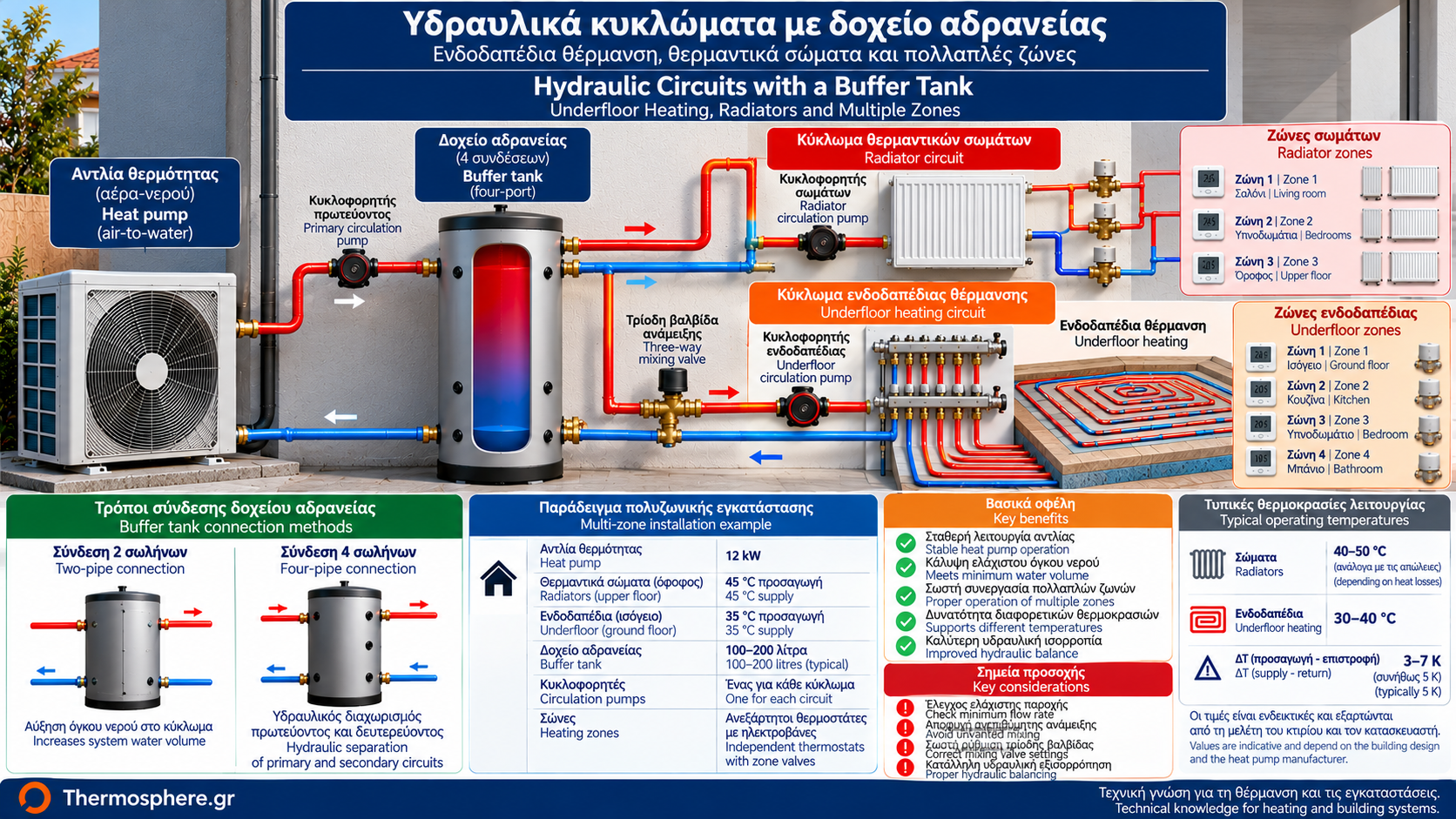
Heat Pump Buffer Tank Connections: Underfloor Heating, Radiators and Multiple Zones
The hydraulic connection between a heat pump and a building’s heating system plays a decisive role in operating reliability and energy efficiency.
In a simple installation, the heat pump may supply an underfloor heating circuit or radiator system directly.
However, when different circuits, independent thermostats, motorized valves and multiple circulation pumps are involved, hydraulic design becomes more complex.
In these cases, a buffer tank may provide additional water volume or, depending on the connection arrangement, hydraulic separation between circuits.
Nevertheless, a buffer tank is not necessary in every installation.
The correct solution depends on heat pump requirements, water flow rates, operating temperatures and zone control strategy.
1. What Are Primary and Secondary Hydraulic Circuits?
In a hydraulically separated installation, two circuits are commonly identified.
Primary circuit: Connects the heat pump to the hydraulic separation point, such as a four-port buffer tank.
Secondary circuit: Transfers water from the separation point to radiators, underfloor heating or other heat emitters.
Each circuit may have its own circulation pump.
This arrangement allows different flow rates without strong direct hydraulic interaction between pumps.
However, hydraulic independence does not eliminate the thermal consequences of unequal flow rates.
2. When Can a Heat Pump Be Connected Directly?
Direct connection is possible when the installation meets manufacturer requirements.
Important conditions include:
Sufficient active water volume.
Guaranteed minimum water flow.
Suitable operating temperatures.
Proper hydraulic balancing.
Compatible thermostat and valve operation.
Compliance with defrost requirements where applicable.
For example, an underfloor heating system with a permanently available manifold may operate without a buffer tank if all technical conditions are satisfied.
Direct connection can reduce complexity and unwanted thermal losses.
3. Buffer Tanks With Underfloor Heating
Underfloor heating normally operates at relatively low water temperatures.
This is advantageous for heat pump efficiency.
The floor’s substantial thermal inertia can also contribute to stable heating operation.
However, the floor’s thermal mass is not equivalent to the active water volume required by the heat pump manufacturer.
The need for a buffer depends on:
Water volume in the circuits.
Number of manifolds.
Presence of thermal actuators.
Thermostat operation.
Minimum heat pump flow rate.
Minimum water volume requirements.
If every zone can close simultaneously, a suitable strategy is required to maintain necessary circulation.
4. Example: A House With Underfloor Heating
Consider a house with:
An air-to-water heat pump.
Underfloor heating throughout.
One central manifold.
Low supply water temperature.
No independent zone valves capable of isolating every circuit.
If total active water volume and available flow meet the unit’s requirements, direct connection may be suitable.
Adding a buffer tank does not automatically improve performance.
Its purpose should be justified by a specific system requirement.
5. What Changes When Multiple Thermostats Are Installed?
In a multi-zone installation, each room may have an independent thermostat.
When the desired room temperature is reached, the thermostat may close the corresponding zone valve.
This reduces available water flow and active system volume.
If only one small zone remains open, the heat pump may experience:
Reduced circulation.
Excessive compressor cycling.
Rapid water temperature changes.
Flow protection faults.
A buffer tank may form part of the solution, but the overall control strategy is equally important.
6. Buffer Tanks With Radiators
Heat pumps can operate with appropriately sized radiators.
Required water temperatures depend on building heat losses and radiator output.
In systems with thermostatic radiator valves, water flow may change continuously.
Buffer tank requirements should be assessed against:
Total water volume.
Minimum flow rate.
Thermostatic valve operation.
Radiator sizing.
Minimum heat pump thermal output.
A buffer tank cannot compensate for inadequate radiator heat-emitting capacity.
If radiators require excessively high supply temperatures, the underlying design issue must be addressed.
7. Mixed Systems: Underfloor Heating and Radiators
A building may have underfloor heating on the ground floor and radiators upstairs.
These circuits may require different water temperatures.
For example, under particular design conditions:
Radiators may require a 45°C supply temperature.
Underfloor heating may require 35°C.
These are illustrative values, not universal requirements.
A mixing circuit may therefore be used for underfloor heating.
If a buffer tank is required, it should be integrated into a hydraulic arrangement that serves both circuits correctly.
8. What Does a Three-Way Mixing Valve Do?
A three-way mixing valve can combine warmer supply water with cooler return water.
Its purpose is to deliver the required temperature to a particular heating circuit.
For example, if the main circuit operates at 45°C, a mixing valve can regulate a lower temperature for underfloor heating.
Its operation must be coordinated with:
Suitable temperature sensing.
Appropriate controls.
Compatible circulation pump.
Required temperature safety protection.
A mixing valve does not replace hydraulic separation.
These are different functions.
9. Why Are Separate Circulation Pumps Sometimes Needed?
Primary and secondary circuits may have different flow and pressure requirements.
For example:
The primary circuit must maintain the heat pump’s required flow.
Underfloor heating must overcome the pressure losses of its loops.
Radiator circuits may have different hydraulic characteristics.
Hydraulic separation allows circulation pumps to operate without excessive direct hydraulic interaction.
However, this does not mean that every heating zone must have its own pump.
Pump selection must follow the hydraulic design.
10. How Does a Four-Port Buffer Tank Work?
A four-port buffer tank may include:
Supply from the heat pump.
Return to the heat pump.
Supply to the heating distribution system.
Return from the heating distribution system.
This arrangement can provide hydraulic separation between primary and secondary circuits.
However, differences in flow rates may cause water mixing inside the tank.
Such mixing affects supply temperatures delivered to the emitters and return temperatures reaching the heat pump.
A four-port connection is therefore not always the most efficient option.
11. What Happens When Primary Flow Is Higher?
Assume:
Heat pump primary flow: 1,500 L/h.
Secondary heating flow: 1,000 L/h.
The difference is 500 L/h.
In an idealized hydraulic separator, the excess flow may travel internally from supply toward return.
Some warmer water therefore returns to the heat pump without passing through the heat emitters.
The actual effect depends on tank geometry, temperatures and operating conditions.
Poor flow balancing may negatively affect efficiency.
12. What Happens When Secondary Flow Is Higher?
Assume:
Primary flow: 1,000 L/h.
Secondary flow: 1,500 L/h.
The difference is 500 L/h.
In an idealized arrangement, some cooler return water may mix with the supply feeding the secondary circuit.
This can reduce the supply temperature reaching radiators or underfloor heating.
The controller may then increase the heat pump’s production temperature to meet heating demand.
This can reduce COP.
13. Example: Calculating Water Flow Rate
For water, the following approximate relationship is commonly used:
P = 1.163 × Q × ΔT
Where:
P is transferred thermal power in kW.
Q is water flow in m³/h.
ΔT is supply-to-return temperature difference in K.
For 10 kW and ΔT of 5 K:
Q = 10 / (1.163 × 5)
Q ≈ 1.72 m³/h
This is approximately 1,720 litres per hour.
The formula is approximate for water. Glycol mixtures require their specific thermophysical properties.
Design flow must also meet manufacturer requirements.
14. Why Is Hydraulic Balancing Important?
Hydraulic balancing ensures that each circuit receives the required water flow.
Without proper balancing, problems may include:
Uneven room heating.
Pipework noise.
Excessive flow through some circuits.
Insufficient flow through others.
Increased pump electricity consumption.
Unstable valve operation.
A buffer tank does not replace proper circuit balancing.
15. What Is the Role of Zone Valves?
Zone valves allow independent operation of different parts of a building.
They may separate:
Ground floor.
Upper floor.
Bedrooms.
Living areas.
Spaces with different heating schedules.
However, when several zones close, total flow can decrease significantly.
The system design must ensure that the heat pump remains within its permitted operating limits.
In some arrangements, hydraulic separation and independent primary circulation provide this protection.
16. Can a Differential Pressure Bypass Valve Be Used?
A differential pressure bypass valve can limit increases in differential pressure when heating zones close.
However, it is not a universal solution for every heat pump.
In particular:
It does not increase active water volume.
It does not necessarily provide adequate compressor runtime.
It may create unwanted recirculation.
It must be compatible with the hydraulic and control design.
Its use should be justified by the installation design.
17. How Is Weather Compensation Affected?
Weather compensation adjusts supply water temperature according to outdoor conditions and the control strategy.
Its purpose is to produce water at the lowest temperature sufficient to heat the building.
In mixed systems, weather compensation must work with the needs of different circuits.
If a buffer tank causes significant mixing, the temperature produced by the heat pump may differ from the temperature reaching the heat emitters.
Sensor placement and controller settings must account for this difference.
18. Practical Example: Two Floors With Independent Thermostats
Consider a house with:
A nominal 12 kW heat pump.
Underfloor heating on the ground floor.
Radiators upstairs.
Two independent thermostats.
The ground floor may require a lower supply temperature than the upper floor.
The installation should be assessed for:
Actual building heat losses.
Required temperature of each circuit.
Required water flow rates.
Operation when only one floor requests heating.
Available water volume.
Mixing and control strategy.
A buffer tank may help, but it cannot resolve every system requirement on its own.
19. Practical Example: Five Underfloor Heating Zones
A house has five underfloor heating zones with independent thermal actuators.
When all zones are open, available flow may be sufficient.
However, when only one small zone remains open, flow and active volume may fall below the required limits.
The solution must consider:
Zone control logic.
Minimum required flow.
Minimum water volume.
Possibility of maintaining open circuits.
Need for hydraulic separation.
Installing a buffer without checking these factors may not solve the problem.
20. Choosing the Appropriate Hydraulic Arrangement
Installation type | Main technical consideration |
Single underfloor heating zone | Assess suitability of direct connection |
Underfloor heating with multiple zone valves | Check minimum flow and active volume |
Radiators with thermostatic valves | Assess variable flow conditions |
Underfloor heating and radiators | Check different temperatures and mixing |
Multiple circulation pumps | Assess need for hydraulic separation |
Four-port buffer tank | Check mixing and flow balance |
This table is a guide to technical assessment, not a ready-made installation schematic.
21. Common Installation Mistakes
Mistake 1: Installing a buffer without a demonstrated need.
This increases complexity without necessarily providing benefits.
Mistake 2: Incorrect temperature sensor location.
This may cause incorrect temperature control.
Mistake 3: Insufficient primary flow.
This can activate heat pump protection functions.
Mistake 4: Excessive flow imbalance.
This may create unwanted mixing.
Mistake 5: Incorrect mixing valve settings.
This may produce unsuitable secondary circuit temperatures.
Mistake 6: Ignoring operation with closed zones.
This may reduce active volume and water flow.
Mistake 7: Inadequate insulation.
This increases heat losses from tanks and pipework.
22. What Should Be Checked During Commissioning?
Depending on the installation, commissioning should verify:
Correct flow direction.
Circulation pump operation.
Circuit flow rates.
Supply and return temperatures.
Zone valve operation.
Mixing valve settings.
Thermostat and heat pump coordination.
Part-load operation.
Minimum required water flow.
Compliance with manufacturer instructions.
Testing should also include conditions where only a few zones are operating.
23. Frequently Asked Questions
Does Underfloor Heating Always Need a Buffer Tank?
No. It depends on active water volume, flow, zoning and heat pump requirements.
Can a Heat Pump Connect Directly to Radiators?
Yes, if the unit and hydraulic circuit requirements are satisfied.
Are Two Circulation Pumps Always Needed With a Buffer Tank?
No. Pump requirements depend on the hydraulic arrangement.
Can Underfloor Heating and Radiators Share One Heat Pump?
Yes, with suitable temperature, flow and control design.
Why Is a Three-Way Mixing Valve Used?
It can provide a lower supply temperature to a circuit that requires it.
Does a Buffer Tank Always Reduce Compressor Cycling?
No. The result depends on active volume, minimum heat pump output and control strategy.
Can a Four-Port Buffer Reduce COP?
Yes, if mixing causes higher production temperatures or other efficiency penalties.
What Happens When All Zones Close?
The installation must include a strategy that maintains the heat pump’s safe operating and circulation requirements.
Is Hydraulic Separation Mandatory in Every Multi-Zone System?
No. It depends on hydraulic design and compatibility between pumps and controls.
What Is the Most Important Design Criterion?
Compatibility between the heat pump, flow rates, active water volume, operating temperatures and control strategy.
Conclusion
A buffer tank can be useful in heat pump installations with underfloor heating, radiators and multiple zones.
However, its presence alone does not guarantee correct hydraulic operation.
A reliable installation requires suitable pump selection, hydraulic balancing, temperature control and coordination between automation components.
The most efficient hydraulic arrangement is the one that satisfies the heat pump and building requirements without unnecessary connections, unwanted mixing or additional thermal losses.
The examples in this article are illustrative and do not replace an installation design or manufacturer-approved hydraulic diagrams.
Thermosphere.gr — Technical knowledge for heating and building systems.