
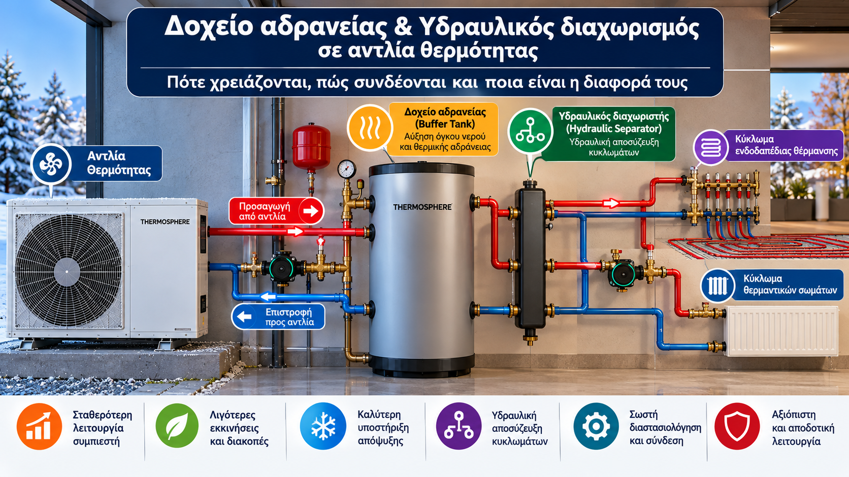
Heat Pump Buffer Tanks and Hydraulic Separation: When They Are Needed and How They Work
Correct hydronic design is essential for efficient and reliable heat pump operation.
One of the most common questions during installation design is whether a buffer tank or hydraulic separator is required.
Although these components can sometimes perform overlapping functions, they are not identical.
A buffer tank primarily increases the available water volume and thermal inertia of the system, while a hydraulic separator allows two circuits to operate with different water flow rates.
In some installations, a correctly connected buffer tank can perform both functions.
1. What Is a Buffer Tank?
A buffer tank is an insulated water vessel installed within a hydronic heating system.
Its primary purpose is to increase the system’s thermal capacity.
Water stores thermal energy, so increasing the available volume can slow temperature changes when heating output or demand varies.
This can support more stable compressor operation, particularly in systems with limited active water volume.
A buffer tank is not the same as an expansion vessel.
An expansion vessel accommodates changes in water volume caused by temperature, while a buffer tank increases thermal storage capacity.
2. Why Might a Heat Pump Need a Buffer Tank?
Meeting Minimum Water Volume Requirements
Many manufacturers specify a minimum active water volume for correct heat pump operation.
This requirement may relate to:
Operating stability.
Limiting excessive compressor cycling.
Providing thermal energy during defrost.
Control system requirements.
If the installation does not provide sufficient active volume, an additional tank may be necessary.
Reducing Frequent Compressor Cycling
When the minimum heat pump output exceeds the building’s heating demand, water temperature can rise rapidly.
The compressor then stops and restarts after the water cools.
Increasing active water volume can extend operating cycles.
However, a buffer tank does not automatically solve oversizing or incorrect control settings.
Supporting Defrost
During defrost operation, an air-to-water heat pump may temporarily extract heat from the hydronic circuit.
Adequate active water volume helps provide the necessary thermal energy.
The actual requirement depends on manufacturer specifications.
3. Does Every Heat Pump Need a Buffer Tank?
No.
A properly designed installation may operate without an additional buffer tank.
The decision depends on:
Manufacturer minimum water volume requirements.
Available water flow.
Minimum compressor heating output.
Heating zone control.
Heat emitter type.
Hydronic system configuration.
For example, an underfloor heating system with sufficient active water volume and stable circulation may not require an additional tank.
A system with low water volume and multiple independently closing zones may require a different hydronic arrangement.
The decision should be based on engineering assessment rather than a universal rule.
4. What Is a Hydraulic Separator?
A hydraulic separator, also called a low-loss header, allows two hydronic circuits to operate with different flow rates.
These circuits are commonly described as:
Primary circuit: The heat pump circuit.
Secondary circuit: The distribution circuit serving underfloor heating, radiators or other heat emitters.
The separator reduces hydraulic interaction between circulation pumps.
As a result, the secondary pump has less influence on primary circuit flow.
However, hydraulic separation does not guarantee identical water temperatures in both circuits.
5. Buffer Tank vs Hydraulic Separator
Feature | Buffer Tank | Hydraulic Separator |
Main purpose | Increase thermal capacity | Hydraulic decoupling |
Heat storage | Depends on tank volume | Usually limited |
Additional water volume | Yes | Small |
Different circuit flow rates | With suitable connections | Yes |
Temperature mixing | Depends on configuration | Depends on flow balance |
Main selection criterion | Water volume and thermal inertia | Hydraulic independence |
A suitably designed four-port buffer tank can also provide hydraulic separation.
6. Two-Pipe Buffer Tank Connections
A two-pipe buffer arrangement adds water volume to the hydronic circuit.
Depending on the design, it may be installed in series or in a suitable bypass configuration.
A series connection in the return line is used in some systems to increase active water volume without necessarily creating separate primary and secondary circuits.
Advantages
Relatively simple hydraulic arrangement.
Increased available water volume.
Potential to limit unnecessary mixing in suitable configurations.
Limitations
A two-pipe tank does not automatically provide hydraulic decoupling.
The additional water volume is useful only when it remains available under the operating conditions for which it is required.
7. Four-Pipe Buffer Tank Connections
In a four-pipe arrangement, the buffer tank connects the primary heat pump circuit to the secondary distribution circuit.
The connections typically include:
Supply from the heat pump.
Return to the heat pump.
Supply to the heating distribution system.
Return from the heating distribution system.
This arrangement can accommodate different flow rates.
Potential Drawback: Temperature Mixing
If secondary flow exceeds primary flow, some cooler return water may mix with the supply water delivered to the heating system.
This can reduce the secondary supply temperature.
Under different flow conditions, some hot primary supply water may return toward the heat pump without transferring its full available heat to the distribution system.
Both situations can affect efficiency.
Hydraulic separation should therefore be selected when needed and combined with appropriate flow balancing.
8. Which Connection Is Better?
There is no single best arrangement for every installation.
Two-Pipe Arrangement
May be appropriate when the main objective is to increase active water volume and separate primary and secondary flow control is unnecessary.
Four-Pipe Arrangement
May be appropriate when hydraulic decoupling is required, such as in more complex systems with multiple circuits and different flow rates.
The correct choice depends on manufacturer instructions and system design.
9. How Is Buffer Tank Size Calculated?
Buffer capacity should not be selected solely from the nominal heat pump output.
Important factors include:
Minimum active water volume required by the manufacturer.
Existing active system volume.
Minimum compressor heating output.
Desired minimum operating time.
Allowable temperature variation.
Defrost requirements.
Heating zone operation.
Thermal Storage Formula
For water, stored thermal energy can be approximated using:
E (kWh) ≈ 0.001163 × V (L) × ΔT (K)
Where:
E: Thermal energy in kWh.
V: Water volume in litres.
ΔT: Temperature difference in °C or K.
Example: 100-Litre Tank
For 100 litres of water and a usable temperature change of 5°C:
E = 0.001163 × 100 × 5
E ≈ 0.58 kWh
This means 100 litres of water can theoretically store or release approximately 0.58 kWh for a 5°C temperature change.
Actual usable energy depends on hydraulic configuration, thermal stratification and operating conditions.
Example: Minimum Compressor Run Time
Assume the heat pump produces 3 kW more than the instantaneous heating demand.
To absorb that surplus for 10 minutes:
E = 3 × (10/60) = 0.5 kWh
With a usable temperature change of 5°C:
V = 0.5 / (0.001163 × 5)
V ≈ 86 litres
This is the estimated total active water volume needed under the stated assumptions, not necessarily the required capacity of an additional tank.
Existing active system volume must be considered, together with manufacturer requirements.
10. Why Is a Larger Buffer Tank Not Always Better?
A larger tank provides greater thermal capacity but may introduce disadvantages:
Higher equipment and installation cost.
Increased space requirements.
Additional standby heat losses.
More water to heat.
Potentially slower system response.
The objective is to select an appropriate volume rather than simply the largest available tank.
11. Buffer Tanks and Underfloor Heating
Underfloor heating systems often contain significant water volume and have substantial thermal inertia due to the floor structure.
However, the thermal mass of the floor should not automatically be treated as equivalent to the active water volume required by the heat pump manufacturer.
If zone actuators close multiple heating loops, available water volume and flow can decrease.
Design should therefore consider operating conditions with only a limited number of zones open.
12. Buffer Tanks With Radiators or Fan Coils
In radiator systems, available water volume depends on the number, type and size of the radiators.
Fan coil installations may have relatively low active water volume, while zone valves can significantly change water flow.
The need for a buffer tank or hydraulic separator should be assessed based on:
Total active water volume.
Minimum required flow.
Valve operation.
Circulation pump requirements.
Control strategy.
13. Common Installation Mistakes
Installing a Tank Without Calculations
Adding a tank does not automatically improve system performance.
Incorrect Supply and Return Connections
Poor connections can cause unwanted mixing and reduced efficiency.
Incorrect Pump Settings
Large differences between primary and secondary flow rates can affect operating temperatures.
Insufficient Insulation
Heat losses from the tank and pipework increase energy demand.
Ignoring Minimum Flow Requirements
A buffer tank does not eliminate the need to maintain the heat pump’s required minimum water flow.
Incorrect Sensor Placement
Temperature sensor locations must match the hydraulic arrangement and control strategy.
14. How Does a Buffer Tank Affect Electricity Consumption?
A correctly selected buffer tank can improve operating stability and address problems associated with insufficient water volume.
However, it does not automatically reduce electricity consumption.
The overall effect depends on:
Operating temperatures.
Heat losses.
Hydraulic configuration.
Circulation pump operation.
Compressor cycling.
Temperature mixing between circuits.
For heat pumps, avoiding unnecessarily high supply water temperatures is especially important for efficiency.
15. Frequently Asked Questions
Does Every Heat Pump Need a Buffer Tank?
No. The requirement depends on active water volume, flow rate, zone operation and manufacturer instructions.
Is a Buffer Tank the Same as an Expansion Vessel?
No. An expansion vessel accommodates water expansion, while a buffer tank increases thermal storage capacity.
Can a Buffer Tank Act as a Hydraulic Separator?
Yes, when designed and connected appropriately, as in certain four-pipe arrangements.
Is a Two-Pipe or Four-Pipe Buffer Better?
It depends on whether the installation requires only additional water volume or also hydraulic decoupling.
How Many Litres Should a Buffer Tank Have?
There is no universal litres-per-kW rule. Correct sizing requires consideration of active water volume, minimum heat pump output, water flow and manufacturer requirements.
Conclusion
Buffer tanks and hydraulic separators serve different but potentially complementary purposes in heat pump installations.
A buffer tank increases available thermal capacity, while a hydraulic separator allows circuits to operate with different water flow rates.
The correct solution depends on engineering design, manufacturer requirements and the operating characteristics of the complete system.
The best installation is not necessarily the one with the most components, but the one in which every component serves a clearly defined technical purpose.
Thermosphere.gr — Technical knowledge for heating and building systems.