
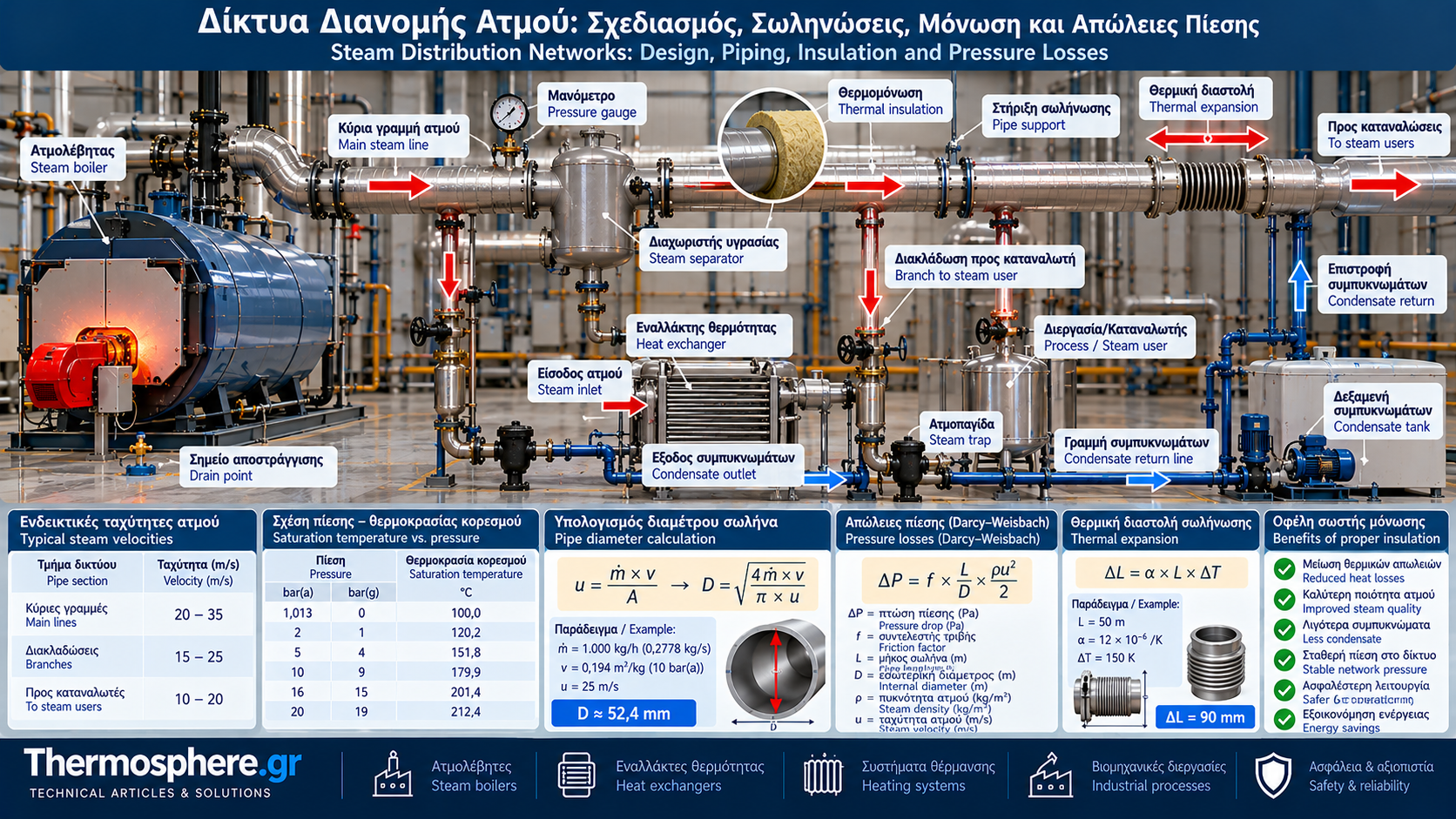
# Steam Distribution Networks: Design, Piping, Insulation and Pressure Losses
## Introduction
A steam distribution network connects steam boilers to industrial consumers. Its design directly affects energy efficiency, pressure stability, steam quality and operating safety.
Even an efficient boiler can supply a poorly performing system when piping is incorrectly sized, insulation is inadequate or condensate drainage is insufficient.
Steam distribution should be designed as an integrated energy transfer system rather than a simple arrangement of connected pipes.
## 1. Main Components of a Steam Distribution System
A typical industrial steam network includes:
- Steam headers.
- Main distribution lines.
- Branch connections to steam users.
- Isolation valves.
- Pressure regulating equipment.
- Moisture separators.
- Drain points and steam traps.
- Pipe supports and expansion provisions.
- Thermal insulation.
- Pressure and temperature instrumentation.
The arrangement depends on process requirements, distances and operating conditions.
## 2. Essential Design Information
Before sizing the piping, determine:
- Normal and maximum steam mass flow in kg/h.
- Steam generation pressure and required consumer pressure.
- Steam temperature and thermodynamic state.
- Pipe lengths and elevation differences.
- Number of fittings and valves.
- Allowable overall pressure drop.
- Startup conditions and load variations.
- Installation environment.
- Drainage and condensate return requirements.
Pressure must be identified clearly as absolute or gauge pressure.
## 3. Steam Velocity Calculation
Steam velocity inside a pipe is calculated using:
u = ṁ × v / A
Where:
u = steam velocity in m/s.
ṁ = mass flow in kg/s.
v = steam specific volume in m³/kg.
A = internal pipe cross-sectional area in m².
For a circular pipe:
A = π × D² / 4.
D represents the actual internal diameter.
Steam velocity depends on mass flow, pressure and pipe diameter.
Pipe sizing should not rely on a single generic velocity rule. Pressure loss, noise, condensate carryover and plant operating requirements must also be considered.
## 4. Pipe Diameter Calculation Example
Consider:
Steam flow: 1,000 kg/h.
Pressure: 10 bar(a).
Dry saturated steam specific volume: approximately 0.194 m³/kg.
Preliminary design velocity: 25 m/s.
Convert mass flow:
ṁ = 1,000 / 3,600 = 0.2778 kg/s.
Volumetric flow:
V̇ = 0.2778 × 0.194 = 0.0539 m³/s.
Required pipe area:
A = 0.0539 / 25 = 0.00216 m².
Internal diameter:
D = √(4A/π) ≈ 0.0524 m.
D ≈ 52.4 mm.
This is a preliminary hydraulic result.
The final nominal pipe size and wall thickness must be selected from actual pipe dimensions and verified against pressure drop, mechanical strength and operating conditions.
## 5. Pressure Losses in Steam Piping
Pressure losses occur due to friction and local flow resistance.
Important contributors include:
- Pipe length.
- Internal roughness.
- Elbows and branches.
- Valves and strainers.
- Changes in cross-section.
- Flow velocity.
For preliminary calculations where density variation is relatively small, the Darcy–Weisbach equation may be used:
ΔP = f × (L/D) × (ρu²/2).
Where:
ΔP = pressure drop in Pa.
f = Darcy friction factor.
L = pipe length in m.
D = internal diameter in m.
ρ = steam density in kg/m³.
u = steam velocity in m/s.
For larger pressure drops, compressible flow calculations are required because steam density and specific volume change along the piping.
## 6. Why Pressure Drop Matters
Excessive pressure drop can result in:
- Insufficient pressure at steam users.
- Reduced saturation temperature.
- Unstable process control.
- Limited available steam flow.
- Increased operating problems.
Pressure at the consumer must satisfy process requirements and account for control equipment losses.
Increasing boiler pressure arbitrarily is not an appropriate substitute for correcting poor piping design.
## 7. Heat Losses from Steam Pipes
Steam pipes continuously transfer heat to their surroundings.
Heat losses depend on:
- Steam temperature.
- Pipe diameter.
- Pipe length.
- Ambient temperature.
- Insulation thermal conductivity.
- Insulation thickness.
- Convection and radiation conditions.
Heat loss can cause steam to condense within the distribution system.
This increases drainage requirements and may reduce steam quality at the point of use.
## 8. Steam Pipe Thermal Insulation
Suitable thermal insulation reduces heat losses and the risk of contact with hot surfaces.
Common materials include:
- Mineral wool.
- Temperature-rated fiberglass.
- Calcium silicate.
- Other approved industrial insulation materials.
Selection depends on operating temperature, environmental exposure, moisture resistance and fire protection requirements.
Valves, flanges and fittings deserve particular attention because they may produce significant local heat losses.
Insulation must not obstruct necessary inspections or access to critical components.
## 9. Heat Loss Calculation
For simplified steady-state heat conduction through cylindrical insulation:
Q̇ = 2πkL(T₁ − T₂) / ln(r₂/r₁).
Where:
Q̇ = heat transfer rate in W.
k = insulation thermal conductivity in W/(m·K).
L = pipe length in m.
T₁ and T₂ = inner and outer insulation surface temperatures.
r₁ and r₂ = corresponding radii.
This equation describes conduction through the insulation only.
Actual heat loss to the environment also requires consideration of convection, radiation and temperature-dependent material properties.
## 10. Thermal Expansion of Steam Piping
Steam pipes expand when heated.
For simple free linear expansion:
ΔL = α × L × ΔT.
Where:
ΔL = change in length.
α = linear thermal expansion coefficient.
L = original length.
ΔT = temperature change.
Example:
Steel pipe length: 50 m.
Illustrative expansion coefficient: 12 × 10⁻⁶ /K.
Temperature rise: 150 K.
ΔL = 12 × 10⁻⁶ × 50 × 150.
ΔL = 0.09 m = 90 mm.
This expansion must be accommodated by suitable piping geometry, supports, guides and expansion compensation arrangements where required.
Mechanical design must consider forces at anchors and equipment connections.
## 11. Condensate Drainage
Even when steam enters a pipe in a dry condition, heat losses may generate condensate.
During startup of a cold steam network, condensate generation can be particularly high.
Effective drainage requires:
- Appropriate pipe slopes.
- Condensate collection pockets.
- Properly selected steam traps.
- Drainage at low points.
- Moisture separators where required.
Drain locations and spacing depend on pipe geometry, design guidance and operating conditions.
## 12. Water Hammer in Steam Systems
Water hammer is a dangerous phenomenon that can occur when accumulated condensate is accelerated by flowing steam or when rapid condensation causes sudden pressure changes.
Possible consequences include:
- Severe vibration.
- Valve and support damage.
- Flange stress.
- Pipe rupture.
- Serious injury risk.
Prevention includes effective drainage, correct pipe slopes, suitable piping arrangements and controlled warm-up procedures.
Cold steam systems must be started according to approved procedures by appropriately trained personnel.
## 13. Branch Connections to Steam Users
Branch connections should minimize the transfer of condensate from the main steam line.
In conventional saturated steam networks, taking steam from the top of the main pipe can help reduce liquid water carryover.
Final arrangements must consider:
- Flow direction.
- Piping geometry.
- Drainage requirements.
- Required pressure.
- Isolation and control equipment.
## 14. Pressure Reducing Stations
Many facilities generate and distribute steam at a higher pressure than individual users require.
Pressure reduction is performed using suitable regulating valves and protective devices.
A pressure reducing station may include:
- Isolation valves.
- Strainer.
- Moisture separator.
- Pressure regulator.
- Pressure gauges.
- Suitable downstream overpressure protection.
- Condensate drainage.
Equipment selection depends on flow, inlet pressure, required outlet pressure and variable-load operation.
## 15. Maintenance and Energy Audits
A steam distribution inspection program should include:
- Insulation inspection.
- Steam leak detection.
- Steam trap testing.
- Pressure monitoring.
- Differential pressure checks at critical locations.
- Pipe support inspection.
- Thermal expansion checks.
- Water hammer monitoring.
- Valve operation checks.
- Drainage system inspection.
Repairing steam leaks and damaged insulation can substantially reduce energy losses.
## 16. Standards and Safety
Design and construction must comply with applicable standards and legislation.
Depending on the scope, relevant European requirements may include:
- Pressure Equipment Directive 2014/68/EU (PED).
- EN 13480 for metallic industrial piping.
- Applicable inspection, maintenance and safe operation requirements.
Material selection, pressure ratings, welding, testing and protective devices must be determined by qualified engineers.
## Conclusion
An efficient steam distribution network requires correct pipe sizing, controlled pressure drop, suitable insulation and effective condensate removal.
Steam velocity and pipe diameter are only part of the design. Thermal expansion, pipe support, water hammer prevention and safe operation of pressure reducing stations are equally important.
Systematic inspection and maintenance help reduce energy losses, improve reliability and protect personnel and equipment.
Thermosphere.gr – Technical Knowledge for Professionals.