
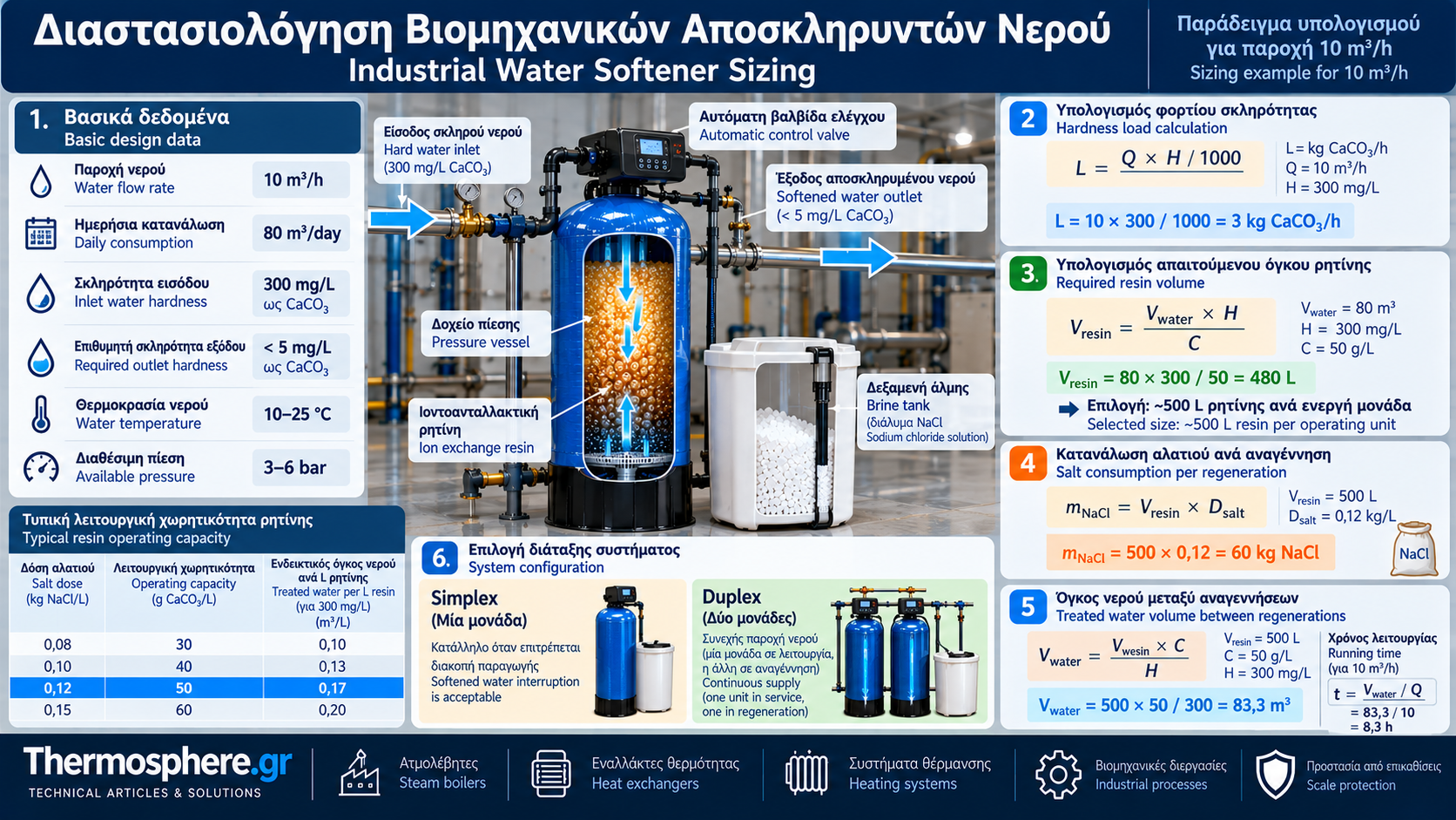
# Industrial Water Softener Sizing: Flow Rate, Hardness and Resin Capacity
## Introduction
Proper industrial water softener sizing is essential for producing consistently low-hardness water and protecting steam boilers, heat exchangers and industrial systems against mineral scale.
A softener cannot be selected on maximum flow rate alone. Feedwater hardness, daily water consumption, resin operating capacity, outlet quality requirements and regeneration frequency must all be considered.
Undersizing can result in premature hardness breakthrough. Oversizing may unnecessarily increase capital and operating costs.
## 1. Essential Design Data
Before selecting equipment, determine:
- Maximum instantaneous water flow in m³/h.
- Average and maximum daily consumption in m³/day.
- Total inlet water hardness.
- Maximum permissible outlet hardness.
- Operating hours and demand variations.
- Available feedwater pressure.
- Water temperature.
- Feedwater chemistry, including iron, manganese, suspended solids and oxidants.
- Space availability and redundancy requirements.
- Regeneration wastewater disposal requirements.
Water analysis must represent actual operating conditions.
## 2. Water Hardness Units
Total hardness is primarily caused by dissolved calcium and magnesium ions.
Common units include:
- mg/L as CaCO₃.
- German degrees (°dH).
- French degrees (°fH).
- mmol/L.
Useful conversions:
1 °dH ≈ 17.85 mg/L as CaCO₃.
1 °fH = 10 mg/L as CaCO₃.
1 mmol/L hardness, expressed as CaCO₃, ≈ 100.09 mg/L as CaCO₃.
Using consistent units is essential for reliable calculations.
## 3. Hardness Load Calculation
Hardness load represents the equivalent mass of calcium carbonate that must be removed.
The basic relationship is:
L = Q × H / 1000
Where:
L = hardness load in kg CaCO₃/h.
Q = water flow in m³/h.
H = hardness in mg/L as CaCO₃.
Example:
Flow rate: 10 m³/h.
Hardness: 300 mg/L as CaCO₃.
L = 10 × 300 / 1000 = 3 kg CaCO₃/h.
The resin must therefore remove an equivalent hardness load of 3 kg CaCO₃ per hour.
## 4. Resin Operating Capacity
Operating capacity describes the amount of hardness removed by a given resin volume between regenerations.
It may be expressed in:
- g CaCO₃/L resin.
- eq/L resin.
- Other manufacturer-specific units.
Operating capacity differs from total theoretical ion exchange capacity.
It depends on:
- Resin type.
- Regeneration salt dose.
- Feedwater hardness and composition.
- Service flow rate.
- Required outlet water quality.
- Regeneration configuration.
Final design must use the manufacturer's operating capacity data.
## 5. Required Resin Volume
The basic sizing equation is:
Vresin = (Vwater × H) / C
Where:
Vresin = resin volume in L.
Vwater = required treated water volume between regenerations in m³.
H = feedwater hardness in mg/L as CaCO₃.
C = resin operating capacity in g CaCO₃/L.
The equation is numerically consistent because 1 m³ of water at 1 mg/L hardness contains 1 g of CaCO₃ equivalent.
Example:
Required treated volume: 80 m³.
Inlet hardness: 300 mg/L as CaCO₃.
Illustrative operating capacity: 50 g CaCO₃/L resin.
Vresin = (80 × 300) / 50 = 480 L.
The theoretical resin requirement is therefore 480 L for the specified hardness load and assumed operating capacity.
Practical sizing must also consider safety reserve, service flow, vessel dimensions and outlet quality specifications.
## 6. Treated Water Volume Between Regenerations
When resin volume is known:
Vwater = (Vresin × C) / H
Example:
Resin volume: 500 L.
Operating capacity: 50 g CaCO₃/L.
Feedwater hardness: 300 mg/L as CaCO₃.
Vwater = (500 × 50) / 300 ≈ 83.3 m³.
This is the theoretical treated volume based on the selected operating capacity.
An appropriate reserve should be included when setting actual regeneration triggers.
## 7. Service Time Between Regenerations
Service time can be calculated as:
t = Vwater / Q
Where:
t = operating time in hours.
Vwater = treated volume in m³.
Q = flow rate in m³/h.
For 83.3 m³ at 10 m³/h:
t = 83.3 / 10 = 8.33 hours.
This does not mean regeneration must occur at exactly 8.33 hours.
Actual scheduling depends on capacity reserve, demand variations and control strategy.
## 8. Flow Rate and Bed Volume Loading
Adequate resin capacity does not automatically mean the softener can handle the required peak flow.
Design checks must include:
- Allowable service flow per unit resin volume.
- Linear velocity through the vessel.
- Resin bed depth.
- Pressure drop.
- Required outlet water quality.
Specific flow is often expressed as bed volumes per hour:
BV/h = Q(L/h) / Vresin(L)
For 10,000 L/h and 500 L resin:
BV/h = 10,000 / 500 = 20 h⁻¹.
Acceptability must be verified against the selected resin and equipment specifications.
## 9. Pressure Vessel Diameter
Vessel diameter affects water velocity through the resin bed.
Superficial velocity is calculated as:
v = Q / A
Where:
v = superficial velocity in m/h.
Q = flow in m³/h.
A = vessel cross-sectional area in m².
For a cylindrical vessel:
A = πD²/4.
Vessel selection must accommodate service flow and, where applicable, backwash requirements with sufficient freeboard for resin bed expansion.
## 10. Salt Consumption Calculation
Salt mass per regeneration can be estimated using:
mNaCl = Vresin × Dsalt
Where:
mNaCl = salt consumption per regeneration in kg.
Vresin = resin volume in L.
Dsalt = specific salt dose in kg/L resin.
Example:
Resin volume: 500 L.
Illustrative salt dose: 0.12 kg NaCl/L resin.
mNaCl = 500 × 0.12 = 60 kg NaCl per regeneration.
This is an illustrative calculation.
The selected salt dose must correspond to the operating capacity assumed in the design.
Using operating capacity data for one regeneration dose and salt consumption for another without recalculation is technically inconsistent.
## 11. Simplex or Duplex Configuration?
### Simplex
A Simplex system contains one resin vessel.
It is suitable where treated water production can be interrupted during regeneration or adequate storage is available.
### Duplex
A Duplex system contains two resin vessels that may operate alternately.
In a duty/standby configuration, one vessel serves the plant while the other regenerates or remains on standby.
For continuous full-capacity service, each duty vessel must be able to handle the required flow while the other is regenerating.
Parallel configurations are also possible, but regeneration periods must be evaluated separately.
## 12. Complete Sizing Example
Consider an industrial installation with:
Maximum flow: 10 m³/h.
Daily consumption: 80 m³.
Inlet hardness: 300 mg/L as CaCO₃.
Required treated volume between regenerations: 80 m³.
Illustrative resin operating capacity: 50 g CaCO₃/L.
Hardness load:
80 × 300 = 24,000 g CaCO₃.
Required resin volume:
24,000 / 50 = 480 L.
A nominal resin volume of approximately 500 L per operating vessel may be evaluated as a preliminary option.
Specific flow check:
10,000 / 500 = 20 BV/h.
Illustrative salt requirement at 0.12 kg/L:
500 × 0.12 = 60 kg per regeneration.
If uninterrupted supply is required, a Duplex arrangement with two adequately sized vessels may be considered.
Important: 500 L is a preliminary sizing result, not a final procurement specification. The selected resin must be verified to provide 50 g/L operating capacity at the assumed salt dose and required outlet water quality.
## 13. Common Sizing Mistakes
Frequent mistakes include:
- Selecting equipment based only on peak flow.
- Ignoring daily consumption.
- Incorrect hardness unit conversion.
- Using theoretical rather than operating resin capacity.
- Omitting capacity reserve.
- Mismatching salt dose and operating capacity.
- Ignoring pressure drop.
- Underestimating regeneration requirements.
- Overlooking feedwater contaminants.
- Assuming all Duplex systems provide full redundancy.
## 14. Final Procurement Checklist
Before purchasing equipment, verify:
- Required outlet water quality.
- Maximum and daily flow.
- Guaranteed operating capacity.
- Resin type and quantity.
- Salt consumption per regeneration.
- Regeneration water consumption.
- Cycle duration.
- Pressure drop.
- Pressure and temperature limits.
- Continuous supply capability.
- Wastewater management requirements.
## Conclusion
Industrial water softener sizing combines hydraulic design with ion exchange capacity calculations.
Flow rate determines hydraulic loading, while hardness and required treated volume determine the load that the resin must remove.
Final equipment selection should rely on documented manufacturer data and actual plant requirements to achieve consistent water quality, reliable operation and controlled regeneration costs.
Thermosphere.gr – Technical Knowledge for Professionals.