
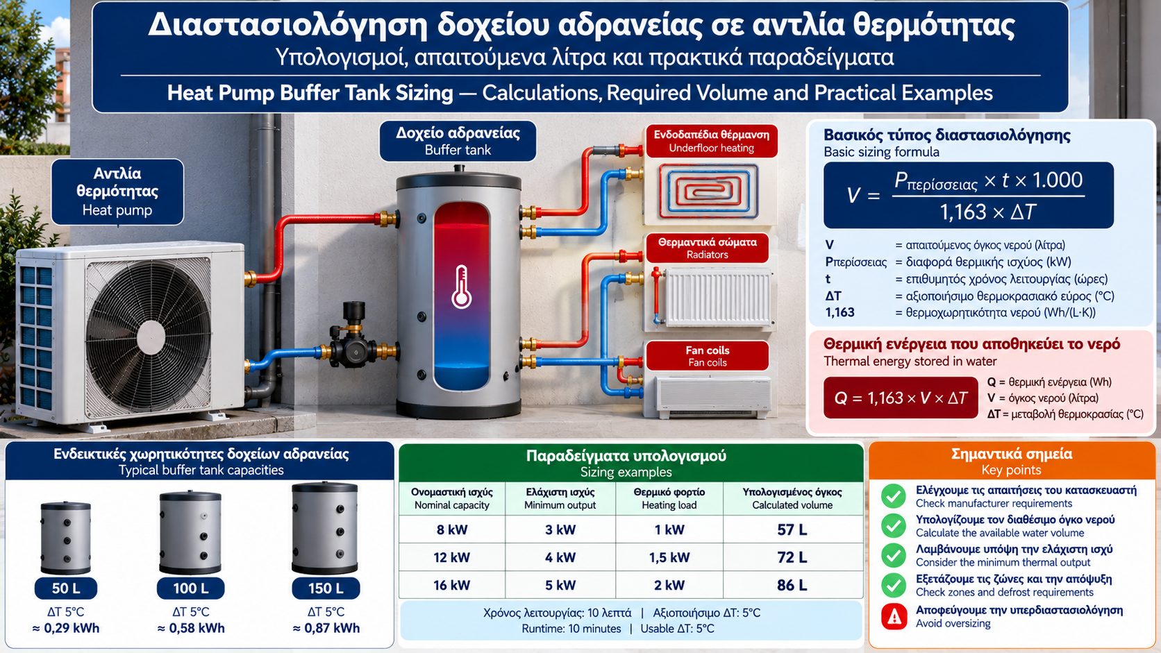
Heat Pump Buffer Tank Sizing: Calculations, Required Volume and Practical Examples
How many litres should a heat pump buffer tank hold? Is 50 litres sufficient, or does the installation require 100, 150 or more?
The answer does not depend solely on the heat pump’s nominal heating capacity.
Correct sizing must consider the manufacturer’s minimum water volume, the thermal capacity of the installation, minimum compressor heating output, defrost requirements and the hydraulic arrangement.
An undersized buffer tank may not provide sufficient thermal inertia. An unnecessarily large tank may increase cost, heat losses and system response time.
This guide explains the sizing methodology, key formulas and practical calculations.
1. Why Must System Water Volume Be Calculated?
A heat pump must operate within the limits specified by its manufacturer.
Some installations already contain sufficient water without an additional buffer tank.
Others, especially systems with small hydraulic circuits or multiple independently controlled zones, may require additional volume.
Buffer sizing aims to:
Meet minimum water volume requirements.
Reduce excessive compressor starts.
Maintain suitable operating conditions.
Support defrost where required.
Ensure compatibility between the heat pump and heating circuits.
A buffer tank should not be selected simply because similar installations commonly include one.
2. Minimum System Volume Versus Buffer Tank Volume
The minimum system water volume specified by a manufacturer is not necessarily equal to the required buffer tank capacity.
For example, if a heat pump requires 50 litres of active water volume and the installation already provides 35 litres that remain available during operation, the theoretical deficit is 15 litres.
This does not automatically mean that a 50-litre tank is required.
However, the existing water volume must remain genuinely connected and available under all relevant operating conditions.
This is especially important in systems with thermostatic valves and motorized zone valves.
3. How Is Total System Water Volume Calculated?
Total water volume includes the relevant hydraulic components.
Examples are:
Water content inside the unit.
Pipework.
Radiators.
Underfloor heating circuits.
Hydraulic components.
Buffer tank, if installed.
The basic relationship is:
Vtotal = Vunit + Vpipes + Vemitters + Vother components + Vbuffer
All values are expressed in litres.
Important: circuits that can be isolated by closed valves should not be counted as guaranteed available volume.
4. Calculating Water Volume in Pipes
For a circular pipe:
V = π × d² × L / 4
Where:
V is volume in m³.
d is internal pipe diameter in metres.
L is pipe length in metres.
Multiply by 1,000 to convert cubic metres into litres.
Example
Consider 50 metres of pipe with an internal diameter of 20 mm.
Convert the diameter:
20 mm = 0.020 m
Calculate:
V = 3.1416 × 0.020² × 50 / 4
V ≈ 0.0157 m³ = 15.7 litres
The pipe contains approximately 15.7 litres of water.
The calculation must use the actual internal diameter rather than simply the nominal pipe designation.
5. How Much Thermal Energy Can Water Store?
The thermal energy stored in water depends on its mass and temperature change.
For practical calculations:
Q = 1.163 × V × ΔT
Where:
Q is thermal energy in Wh.
V is water volume in litres.
ΔT is temperature change in °C or K.
1.163 is the approximate volumetric heat capacity of water in Wh/(L·K).
Example: A 100-Litre Buffer Tank
For a temperature change of 5°C:
Q = 1.163 × 100 × 5
Q = 581.5 Wh ≈ 0.58 kWh
Therefore, 100 litres of water changing temperature by 5°C stores or releases approximately 0.58 kWh of thermal energy.
This illustrates that a typical buffer tank is not equivalent to a large thermal energy storage vessel.
6. Calculating Volume to Reduce Compressor Cycling
An illustrative calculation considers the excess heating output when the heat pump’s minimum thermal output exceeds the building’s heating demand.
The formula is:
V = (Pexcess × t × 1,000) / (1.163 × ΔT)
Where:
V is required active water volume in litres.
Pexcess is excess heating output in kW.
t is the desired runtime in hours.
ΔT is the usable temperature range in K.
Excess output is:
Pexcess = Minimum heat pump thermal output − Building heat load
This is a simplified energy-balance method, not a replacement for the manufacturer’s sizing procedure.
7. Example: An 8 kW Heat Pump
Assume:
Nominal heating capacity: 8 kW.
Minimum thermal output at the selected condition: 3 kW.
Building heating load: 1 kW.
Desired runtime: 10 minutes.
Usable temperature range: 5 K.
Excess output:
3 − 1 = 2 kW
Runtime:
10 / 60 = 0.1667 hours
Calculation:
V = (2 × 0.1667 × 1,000) / (1.163 × 5)
V ≈ 57 litres
This represents the approximate total active water volume required under the stated assumptions.
If the system already contains 35 litres of guaranteed active volume:
57 − 35 = 22 litres.
The theoretical additional volume is approximately 22 litres.
Final selection must also satisfy manufacturer requirements and the actual hydraulic configuration.
8. Example: A 12 kW Heat Pump
Assume:
Nominal capacity: 12 kW.
Minimum thermal output: 4 kW.
Building heating load: 1.5 kW.
Runtime: 10 minutes.
ΔT: 5 K.
Excess output:
4 − 1.5 = 2.5 kW
Calculation:
V = (2.5 × 0.1667 × 1,000) / (1.163 × 5)
V ≈ 72 litres
If 45 litres are already available:
72 − 45 = 27 litres.
The theoretical additional requirement is approximately 27 litres, before considering other design constraints.
9. Example: A 16 kW Heat Pump
Assume:
Nominal capacity: 16 kW.
Minimum thermal output: 5 kW.
Building heating load: 2 kW.
Runtime: 10 minutes.
ΔT: 5 K.
Excess output:
5 − 2 = 3 kW
Calculation:
V = (3 × 0.1667 × 1,000) / (1.163 × 5)
V ≈ 86 litres
If the installation already provides 60 litres of guaranteed active volume, the theoretical deficit is approximately 26 litres.
These examples are hypothetical. Minimum thermal output must be taken from the actual unit’s technical data at the relevant operating condition.
10. Comparison of Sizing Examples
Nominal capacity | Minimum output | Heating load | Calculated volume |
8 kW | 3 kW | 1 kW | 57 L |
12 kW | 4 kW | 1.5 kW | 72 L |
16 kW | 5 kW | 2 kW | 86 L |
All examples use a 10-minute runtime and a 5 K usable temperature range.
These values are not universal buffer tank recommendations based on nominal heat pump capacity.
Two heat pumps with the same nominal output may have different requirements.
11. Is the 10 Litres per kW Rule Reliable?
Rules of thumb specifying a certain number of litres per kW are sometimes used in practice.
However, no single litres-per-kW rule is suitable for every installation.
Actual requirements depend on:
Compressor technology.
Minimum heating output.
Building heating demand.
Existing water volume.
Zone operation.
Defrost requirements.
Control strategy.
Manufacturer-specific requirements always take priority over generic rules of thumb.
12. How Does Inverter Technology Affect Sizing?
An inverter heat pump can adjust its output within a defined range.
The lower its minimum thermal output, the easier it may be to match small heating loads.
This can reduce the need for additional thermal inertia.
However, it does not necessarily eliminate it.
If the building’s heating demand falls below the heat pump’s minimum output, cycling may still occur.
13. How Do Thermostats and Heating Zones Affect Volume?
In multi-zone systems, available water volume may change during operation.
When zone valves or thermostatic valves close, parts of the hydraulic network may become isolated.
This can reduce:
Active water volume.
Available flow rate.
Thermal capacity of the connected circuit.
Sizing must therefore consider the most demanding permitted combination of zone operating conditions.
Adequate water volume does not replace the requirement to maintain minimum water flow.
14. How Does Defrost Affect Buffer Sizing?
Some air-to-water heat pumps use thermal energy from the hydraulic circuit during outdoor coil defrost.
Manufacturers may specify requirements for:
Minimum water volume.
Minimum water temperature.
Available flow rate.
Additional hydraulic components.
These requirements may determine the final volume even if the compressor cycling calculation produces a smaller result.
There is no universal defrost volume that applies to every heat pump.
15. Two-Pipe Versus Four-Pipe Connections
The hydraulic connection determines how the buffer tank participates in system operation.
Two-Pipe Connection
A buffer tank can provide additional water volume within the circuit.
The arrangement must ensure that this volume actually participates under the required operating conditions.
Four-Pipe Connection
A buffer tank may also provide hydraulic separation between primary and secondary circuits.
Differences in flow rates can cause water mixing.
Tank capacity should therefore not be selected independently of hydraulic behaviour.
16. Why Is a Larger Tank Not Always Better?
A larger tank provides greater thermal capacity but can introduce disadvantages.
These include:
Higher purchase cost.
Greater space requirements.
Increased heat losses.
Slower temperature response.
Additional system complexity.
In arrangements that create unwanted mixing, higher supply temperatures may also be required to deliver the same heat to the building.
This can reduce heat pump efficiency.
17. How Does ΔT Affect the Calculation?
For the same excess output and runtime, a larger usable temperature range reduces the theoretical required volume.
For 2 kW of excess output and 10 minutes of runtime:
Usable ΔT | Required volume |
3 K | approximately 96 L |
5 K | approximately 57 L |
7 K | approximately 41 L |
However, ΔT cannot be increased arbitrarily.
It is limited by comfort requirements, control strategy and permitted operating temperatures.
The usable temperature range for energy storage should not be confused with the supply-to-return temperature difference.
18. What Changes When Antifreeze Is Used?
Some installations use a water-glycol mixture for frost protection.
This mixture has different thermophysical properties from pure water.
Consequently:
Specific heat capacity changes.
Density changes.
Hydraulic behaviour is affected.
The 1.163 coefficient is no longer equally accurate.
Accurate calculations should use the properties of the specific mixture at the relevant operating temperature.
19. Recommended Buffer Tank Sizing Procedure
A technically sound process includes:
Identify the exact heat pump model.
Review manufacturer requirements.
Calculate guaranteed available water volume.
Verify minimum flow rate.
Assess zone operation.
Determine minimum thermal output.
Calculate volume for the desired runtime where necessary.
Check defrost requirements.
Select the appropriate hydraulic arrangement.
Verify the final design against manufacturer instructions.
Where different requirements establish different minimum volumes, the most restrictive applicable requirement must be satisfied.
20. Common Sizing Mistakes
The most frequent mistakes include:
Selecting by nominal kW alone. Nominal output is insufficient.
Ignoring existing water volume. This may lead to an unnecessarily large tank.
Counting isolated zones. This overestimates guaranteed available volume.
Confusing volume with flow rate. More litres do not automatically ensure sufficient circulation.
Ignoring defrost requirements. Thermal capacity may be inadequate.
Using an arbitrary ΔT. This can produce unrealistic results.
Oversizing. It increases cost and losses without necessarily improving operation.
21. Frequently Asked Questions
How Many Litres Does an 8 kW Heat Pump Need?
There is no universal value. Minimum system volume, minimum output and existing water volume must be checked.
Is a 50-Litre Buffer Tank Enough?
It may be sufficient for some installations and inadequate for others.
Does Every Inverter Heat Pump Need a Buffer Tank?
No. It depends on the heat pump design and hydraulic circuit.
Can I Install 100 Litres Instead of 50?
A larger capacity is not automatically better. The installation’s actual requirements must be assessed.
Does Underfloor Heating Water Count?
Yes, provided that the relevant volume remains available under the operating conditions being assessed.
Can a Buffer Tank Reduce Short Cycling?
Yes, when insufficient active thermal capacity is a contributing cause and the tank is correctly sized.
Does a Buffer Tank Always Improve COP?
No. Depending on the connection and operating temperatures, it may have a neutral or negative effect on efficiency.
What Should I Check Before Buying a Buffer Tank?
The official manual, active water volume, flow rates, zoning, defrost requirements and hydraulic connection.
Conclusion
Correct buffer tank sizing cannot be based on a universal number of litres per kW.
It requires consideration of manufacturer instructions, actual active water volume, minimum thermal output, defrost requirements and hydraulic operation.
The objective is not to install the largest possible buffer tank, but to provide the necessary active volume with minimal complexity and avoid unnecessary energy losses.
The calculations in this article are educational examples and do not replace an installation design or manufacturer specifications.
Thermosphere.gr — Technical knowledge for heating and building systems.