
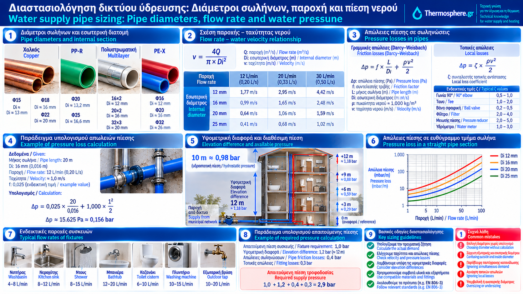
Water Supply Pipe Sizing: Diameter, Flow Rate and Water Pressure
Correct pipe sizing is essential for ensuring adequate flow and pressure at every fixture in a building.
A common mistake is selecting pipe diameters simply because they are frequently used in similar installations.
In reality, sizing depends on water demand, internal pipe diameter, network length, elevation differences and pressure losses.
An undersized pipe can significantly restrict available flow when several fixtures operate simultaneously.
Oversizing can increase installation cost, the volume of water held within the pipes and, in some cases, domestic hot water waiting times.
This Thermosphere.gr guide explains the main principles of water supply pipe sizing, key equations and practical calculation examples.
1. What Is Water Supply Pipe Sizing?
Pipe sizing is the process of selecting appropriate pipe and component dimensions to meet operating requirements.
The design considers:
Design flow rate.
Available pressure.
Internal pipe diameters.
Pipe lengths.
Elevation differences.
Pressure losses.
Fixture requirements.
Simultaneous demand.
The objective is to balance hydraulic performance, cost and water hygiene.
2. What Is Water Flow Rate?
Flow rate describes the volume of water passing through a cross-section per unit of time.
It is commonly represented by Q.
Typical units include:
Litres per second (L/s).
Litres per minute (L/min).
Cubic metres per hour (m³/h).
Useful conversions are:
1 L/s = 60 L/min = 3.6 m³/h
For example:
12 L/min = 0.20 L/s.
Flow rate and pressure are different hydraulic quantities.
3. Pressure Versus Flow Rate
Pressure describes the hydraulic condition of water at a particular point.
Flow rate describes how much water moves through the system over time.
A network may have adequate static pressure when taps are closed but insufficient flow when several fixtures are opened.
Possible causes include:
Small internal pipe diameters.
Long pipe runs.
Blocked filters.
High fitting resistance.
Limited supply capacity.
Static pressure alone is therefore not enough to assess network performance.
4. Outside Diameter Versus Inside Diameter
Plastic and multilayer pipes are often identified by outside diameter and wall thickness.
For example:
20 × 2 mm
This means:
Outside diameter: 20 mm.
Nominal wall thickness: 2 mm.
Nominal internal diameter is calculated as:
Di = De − 2e
Therefore:
Di = 20 − 2 × 2 = 16 mm.
Actual internal diameter should be checked against manufacturer data because tolerances and dimensions vary between systems.
Two pipes with the same outside diameter may have different internal flow areas.
5. Relationship Between Flow, Diameter and Velocity
The continuity equation is:
Q = A × v
Where:
Q is flow rate in m³/s.
A is internal cross-sectional area in m².
v is mean water velocity in m/s.
For a circular pipe:
A = π × Di² / 4
Therefore:
v = 4Q / (π × Di²)
At a constant flow rate, reducing internal diameter increases velocity.
6. Water Velocity Calculation Example
Consider:
Internal diameter: 16 mm.
Flow rate: 12 L/min.
Convert:
Q = 12 / 60,000 = 0.0002 m³/s.
Di = 0.016 m.
The cross-sectional area is:
A = π × 0.016² / 4 ≈ 0.000201 m².
Velocity:
v = 0.0002 / 0.000201 ≈ 0.99 m/s.
With the same flow through a 12 mm internal diameter pipe:
v ≈ 1.77 m/s.
Reducing diameter significantly increases velocity and generally increases pressure losses.
These are calculation examples, not universal allowable velocity limits.
7. What Water Velocity Is Acceptable?
There is no single velocity limit appropriate for every pipe and application.
Acceptable velocity depends on:
Material.
Diameter.
Intended use.
Noise requirements.
Water hammer considerations.
Manufacturer instructions.
Applicable technical standards.
Excessive velocity can increase noise and pressure losses.
Very low velocities in oversized systems may contribute to longer water residence times, depending on usage.
Final sizing requires a combined assessment.
8. What Are Pressure Losses?
As water flows through pipes, some mechanical energy is dissipated by friction and local resistance.
This results in pressure loss along the flow path.
Pressure losses are commonly divided into:
Friction losses: Caused by flow along the pipe.
Local losses: Caused by elbows, tees, valves, couplings, filters and other fittings.
The total loss determines how much pressure remains available at the fixture.
9. Darcy–Weisbach Equation
A fundamental equation for pipe friction pressure loss is:
Δp = f × (L / Di) × (ρv² / 2)
Where:
Δp: pressure loss in Pa.
f: dimensionless Darcy friction factor.
L: pipe length in m.
Di: internal diameter in m.
ρ: water density in kg/m³.
v: mean water velocity in m/s.
The friction factor depends on Reynolds number and relative roughness.
Real designs require appropriate material data and reliable calculation methods.
10. Pressure Loss Example
Consider a straight pipe section with:
Length L = 20 m.
Internal diameter Di = 16 mm.
Velocity v ≈ 1 m/s.
Water density ρ ≈ 1,000 kg/m³.
Assumed Darcy friction factor f = 0.025.
Then:
Δp = 0.025 × (20 / 0.016) × (1,000 × 1² / 2).
Result:
Δp ≈ 15,625 Pa.
Since 1 bar = 100,000 Pa:
Δp ≈ 0.156 bar.
This is the calculated friction loss under the stated assumptions.
Local fitting losses and elevation effects are not included.
11. What Are Local Pressure Losses?
Local losses arise from components that change flow direction or hydraulic conditions.
They may be estimated using:
Δplocal = ζ × ρv² / 2
Where ζ is the local loss coefficient.
Its value depends on the component and its geometry.
Elbows, tees and valves do not necessarily have equal resistance.
Manufacturers may provide pressure loss curves or Kv values for specific products.
12. How Does Elevation Affect Pressure?
Elevation differences affect the pressure available at fixtures.
For water under ordinary conditions:
10 m elevation difference ≈ 0.98 bar.
For a fixture 12 m above the reference point:
Elevation pressure difference ≈ 1.18 bar.
This hydraulic head is needed simply to overcome the elevation difference.
Additional pressure is required to overcome network losses and provide adequate operating pressure at the fixture.
13. How Is Required Supply Pressure Estimated?
A simplified relationship is:
Supply pressure ≥ Required fixture pressure + Elevation pressure difference + Pipe friction losses + Fitting losses
All quantities must use consistent units and appropriate flowing conditions.
Example:
Required fixture dynamic pressure: 1.0 bar.
Elevation pressure difference: 1.2 bar.
Combined pipe and fitting losses: 0.5 bar.
Therefore:
Supply pressure ≥ 1.0 + 1.2 + 0.5.
Required pressure ≈ 2.7 bar.
This is an illustrative calculation, not a substitute for a complete hydraulic design.
14. What Is Simultaneous Water Demand?
Not all plumbing fixtures operate at the same time.
The design flow rate is therefore not always the sum of the maximum flow rates of every fixture.
Pipe sizing uses methods for estimating probable simultaneous demand.
The approach depends on:
Building type.
Number of fixtures.
Usage patterns.
Applicable calculation methods.
EN 806-3 provides a simplified sizing method for installations within its scope.
An arbitrary diversity factor should not be applied to every system.
15. Why Is Counting Taps Not Enough?
Two buildings with the same number of taps may have very different water demand.
For example, residential and commercial buildings may have different simultaneous usage patterns.
Fixtures may also have different minimum pressure and flow requirements.
Sizing must therefore reflect actual operating requirements.
16. How Do Fittings Affect Pipe Sizing?
Real plumbing networks contain more than straight pipe runs.
Components may include:
Elbows.
Tees.
Isolation valves.
Filters.
Water meters.
Pressure reducing valves.
Manifolds.
Special couplings.
Each component can introduce additional resistance.
Special attention is required where fittings have restricted internal flow passages.
A fitting’s nominal size does not guarantee that its internal flow area equals the pipe’s internal area.
17. Small or Large Pipe Diameter?
A smaller diameter generally:
Reduces the volume of water in the pipe.
May reduce initial material costs.
Increases velocity at a given flow rate.
Increases pressure losses.
A larger diameter generally:
Reduces velocity at the same flow rate.
Reduces pipe friction losses.
Increases water volume.
May increase cost and hot water waiting time.
The correct diameter meets design demand without unnecessary oversizing.
18. Practical Diameter Comparison
At a constant flow rate of 12 L/min:
Internal diameter | Mean velocity |
12 mm | 1.77 m/s |
16 mm | 0.99 m/s |
20 mm | 0.64 m/s |
25 mm | 0.41 m/s |
These values follow from the continuity equation.
They are not a recommended pipe size table.
Final selection requires checking pressure, losses, application and specifications.
19. Common Pipe Sizing Mistakes
Typical mistakes include:
Choosing pipe sizes without calculation.
Confusing outside and inside diameters.
Ignoring simultaneous demand.
Considering static pressure only.
Ignoring elevation differences.
Omitting local losses.
Oversizing pipes unnecessarily.
Using generic sizing tables without checking applicability.
Ignoring fixture pressure requirements.
Failing to verify performance after installation.
20. Frequently Asked Questions
What Pipe Diameter Does a House Need?
There is no universal size. Selection depends on design flow, pipe routes, available pressure and system specifications.
Is a 20 mm Pipe Enough for a Bathroom?
Outside diameter alone is insufficient to answer. Wall thickness, demand, length and pressure losses must be considered.
Why Does Water Pressure Drop When Two Taps Are Open?
Higher flow causes increased pressure losses. The supply or a component may also restrict flow.
Will a Larger Pipe Increase Water Pressure?
A larger pipe may reduce friction losses during flow, but it does not independently increase static supply pressure.
Which Is More Important, Pressure or Flow?
Both matter. A fixture requires adequate flow at a suitable dynamic pressure.
How Is Water Velocity Calculated?
From flow rate and internal pipe area using v = Q/A.
Conclusion
Correct water supply pipe sizing requires combined assessment of flow rate, internal diameter, velocity, elevation and pressure losses.
Selecting pipes solely by experience or outside diameter can lead to poor performance or unnecessary oversizing.
A properly calculated system provides the required quantity of water at suitable pressure while supporting reliable and efficient operation.
Technical References and Further Reading
EN 806-2: Specifications for installations inside buildings conveying water for human consumption — Design.
EN 806-3: Specifications for installations inside buildings conveying water for human consumption — Pipe sizing — Simplified method.
EN 806-4: Specifications for installations inside buildings conveying water for human consumption — Installation.
EN 806-5: Specifications for installations inside buildings conveying water for human consumption — Operation and maintenance.
Darcy–Weisbach equation: Fundamental equation for calculating pipe friction pressure losses.
CEN-CENELEC: https://www.cencenelec.eu/
Technical requirements must be verified against current standards, national regulations and manufacturer instructions.
Note: Numerical examples are provided for educational purposes. Final sizing of a real installation requires a complete hydraulic assessment and verification of operating conditions.
Thermosphere.gr — Technical knowledge for water supply and heating systems.