
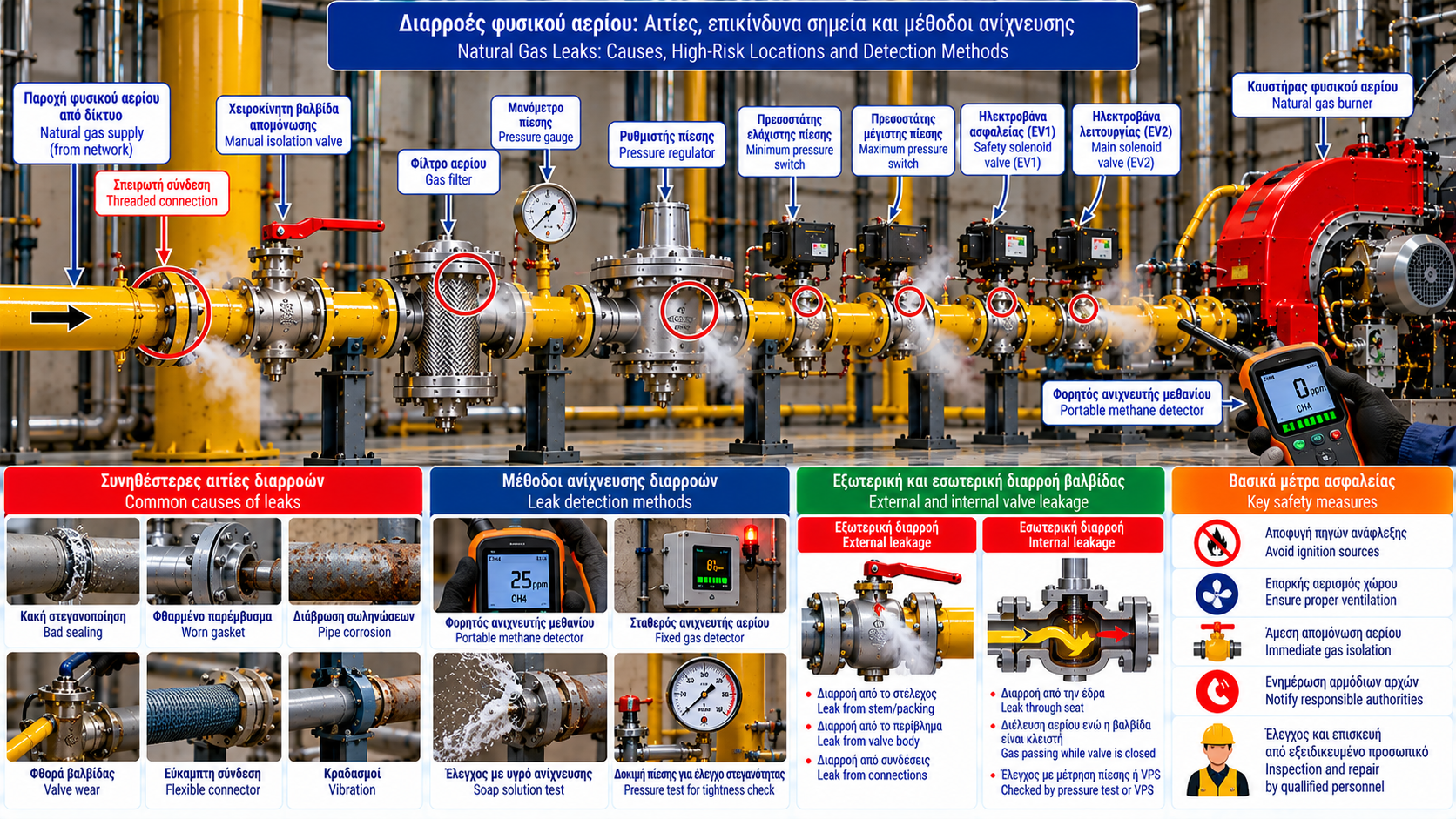
Natural Gas Leaks: Causes, High-Risk Locations and Detection Methods
Natural gas leaks are among the most significant hazards in gas supply systems serving industrial burners, boilers and thermal energy installations.
Even a relatively small leak can become dangerous if gas accumulates in an inadequately ventilated area and encounters an ignition source.
Effective prevention depends on proper network design, suitable components, scheduled tightness inspections and reliable gas detection systems.
1. Why Are Natural Gas Leaks Dangerous?
Natural gas consists mainly of methane, a flammable gas that can form explosive mixtures with air.
Approximate methane flammability limits in air are:
Lower Explosive Limit (LEL): Approximately 5% by volume.
Upper Explosive Limit (UEL): Approximately 15% by volume.
Actual values depend on gas composition and operating conditions.
Natural gas is generally lighter than air and may accumulate near ceilings or other high locations in poorly ventilated spaces.
Actual dispersion depends on temperature, ventilation, room geometry and leak direction.
2. Common Gas Leak Locations
Important inspection locations include:
Threaded joints.
Flanges and gaskets.
Manual isolation valves.
Pressure regulators.
Gas filters.
Automatic shut-off valves and gas trains.
Approved flexible connections.
Pressure test points.
Corroded or mechanically stressed piping.
The presence of multiple joints does not prove leakage, but it creates additional locations requiring inspection.
3. Threaded Connection Leaks
Threaded joints are used in suitable applications within the applicable design limits.
Potential leakage causes include unsuitable sealing compounds, incorrect assembly, mechanical stress, vibration, corrosion and repeated intervention without proper resealing.
Connections must be installed and tested according to the applicable specifications.
4. Flange Leakage
Flanged joints are common in larger gas piping systems.
Their tightness depends on the compatibility of flanges, gaskets, bolts and operating conditions.
Possible failure causes include damaged gaskets, unsuitable sealing materials, uneven tightening, misalignment, thermal stress and corrosion.
Retightening a live gas connection must not be assumed to be a safe corrective measure.
5. Leakage from Gas Valves
Gas valves contain sealing surfaces and, depending on design, stem seals or other moving-part seals.
Two different leakage mechanisms must be distinguished.
External leakage: Gas escapes from the valve body, connections or seals into the surrounding environment.
Internal leakage: Gas passes through the seat of a valve that should be closed.
External valve tightness does not prove internal seat tightness.
These conditions require different testing methods.
6. Pressure Regulator Leakage
Gas pressure regulators contain mechanisms that control gas flow.
Depending on their design, they may include diaphragms, springs, seats and venting or relief arrangements.
Potential problems include sealing deterioration, diaphragm failure, connection leakage, internal seat failure and unintended gas release.
Gas detected near a regulator vent must be evaluated against the specific regulator’s design and operating requirements.
7. Leakage in Industrial Burner Gas Trains
A gas train contains fuel supply and safety components.
Depending on configuration, it may include a filter, pressure regulator, pressure switches, automatic shut-off valves, test points and valve proving equipment.
Potential leakage points include component connections, housings and seals.
Automatic shut-off valves may also require internal seat tightness assessment.
8. Corrosion-Related Leakage
Corrosion can reduce the wall thickness of metallic gas piping.
Risk depends on materials, environmental conditions, protective coatings and exposure duration.
Particular attention is required in damp or chemically aggressive environments and where protective coatings have been damaged.
Network integrity should be assessed using appropriate inspection methods.
9. Vibration and Mechanical Stress
Vibration, inadequate pipe support and unexpected movement can stress gas piping connections.
Possible consequences include joint deterioration, material fatigue and seal damage.
Proper pipe support and avoidance of excessive mechanical loads are essential design considerations.
10. Can Gas Leaks Be Detected by Smell?
Methane is naturally odorless.
Odorants are added to natural gas distributed for many applications to help people recognize potential leaks.
However, smell is not a reliable method of certifying gas tightness.
Odor perception varies, and not all industrial gas streams are necessarily odorized.
The absence of smell does not prove the absence of a leak.
11. Portable Gas Leak Detectors
Portable detectors are used by trained personnel to identify the presence of combustible gas.
Depending on the instrument, readings may be displayed in:
ppm.
%LEL.
Percentage by volume.
These units must be interpreted according to the instrument’s measurement range and calibration.
For methane, assuming an LEL of approximately 5% by volume, a reading of 10% LEL corresponds to approximately 0.5% methane by volume.
This conversion is illustrative and does not replace instrument specifications.
12. Fixed Methane Detection Systems
Suitable industrial installations may use fixed gas detectors for continuous monitoring.
A system may include methane sensors, a control panel, audible and visual alarms, ventilation interfaces, automatic gas isolation commands and sensor fault indications.
Detector placement and response logic must follow a risk assessment and applicable technical requirements.
13. Approved Leak Detection Fluids
For certain accessible joints, qualified personnel may use approved leak detection fluids.
Bubble formation can indicate escaping gas.
This method must only be used where permitted by equipment and product specifications.
Open flames must never be used to search for gas leaks.
14. Pressure-Based Tightness Testing
Gas piping tightness may be assessed using an approved pressure test procedure and suitable test medium.
The procedure depends on the installation type, allowable pressure, materials, components, applicable standards and construction or operating stage.
The absence of an obvious pressure drop during an improvised test does not constitute a valid tightness certificate.
Testing must be performed by competent personnel following approved procedures.
15. Internal Tightness of Automatic Gas Valves
Internal tightness of automatic shut-off valves is separate from piping external tightness.
Some installations use a Valve Proving System (VPS) to assess valve tightness through a specified test sequence.
Valve proving does not replace the general inspection of the installation for external gas leaks.
16. Gas Leak Diagnostic Table
Location | Possible Cause | Inspection Focus |
Threaded joint | Seal failure | Approved local leak testing |
Flange | Gasket deterioration | External tightness inspection |
Valve stem | Seal deterioration | Manufacturer-approved inspection |
Shut-off valve seat | Internal leakage | Specified valve tightness test |
Regulator | Diaphragm or seat failure | Specialist regulator assessment |
Gas piping | Corrosion or mechanical damage | Integrity inspection |
Pressure test point | Seal failure | Approved connection inspection |
Flexible connector | Aging or mechanical stress | Condition and suitability assessment |
17. What Should Be Done If a Leak Is Suspected?
If a natural gas leak is suspected:
Leave the affected area and warn others.
Do not smoke, use open flames or operate electrical switches in the suspected area.
Do not attempt improvised leak detection.
Follow emergency isolation procedures only if they can be carried out without exposure to danger.
Contact the gas network operator, emergency services or responsible safety personnel from a safe location.
Do not restart the installation until the required inspections and authorization have been completed.
For immediate emergencies in Greece, call 112 from a safe location.
18. Preventive Inspection
A preventive maintenance program may include visual piping inspections, pipe support checks, valve and regulator inspections, scheduled tightness tests, gas detector checks, alarm verification and documented corrective actions.
Inspection frequency and scope must reflect installation requirements, manufacturer instructions and applicable regulations.
19. Technical Standards
Relevant references include:
EN 15001-1: Design, construction, inspection and testing of gas installations within its scope.
EN 15001-2: Operation and maintenance requirements for applicable gas installations.
EN 1775: Gas pipework for buildings within its specified scope.
EN 60079-29-1: Performance requirements for flammable gas detectors.
EN 60079-29-2: Guidance on selection, installation, use and maintenance of flammable gas detectors.
EN 1643: Valve proving systems.
Applicability depends on the installation category and national requirements.
Conclusion
Natural gas leaks may originate from joints, flanges, valves, regulators, piping and other components.
Prevention cannot rely on odor recognition or occasional visual inspection alone.
Proper engineering design, suitable detection instruments, scheduled inspections and documented safety procedures are essential.
In industrial installations, distinguishing external leakage from internal valve seat leakage is particularly important when selecting the appropriate inspection method.