
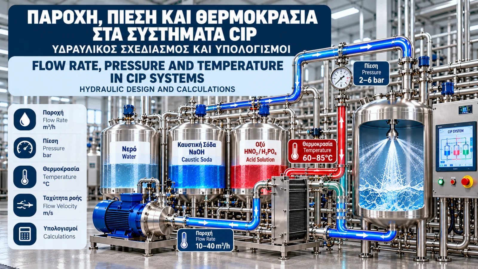
Flow Rate, Pressure and Temperature in CIP Systems: Hydraulic Design and Calculations
Introduction
The performance of a Cleaning in Place (CIP) system depends on more than cleaning chemicals. Flow rate, fluid velocity, pressure, temperature and contact time are critical to removing residues from internal equipment surfaces.
Even when an appropriate chemical solution is used, cleaning can be ineffective because of insufficient flow velocity, excessive hydraulic resistance or inadequate heating capacity.
Proper CIP engineering requires hydraulic calculations, suitable pump selection, thermal sizing and verification of actual operating conditions.
1. The Role of Flow Rate in CIP
Flow rate represents the volume of cleaning solution passing through a cross-section per unit time.
Common units include m³/h and L/min.
For a circular pipe:
Q = A × v
Since the internal cross-sectional area is A = πD²/4:
Q = (πD²/4) × v
Where:
Q = volumetric flow rate (m³/s).
A = internal cross-sectional area (m²).
D = actual internal pipe diameter (m).
v = average fluid velocity (m/s).
The actual internal diameter should be used rather than relying only on nominal pipe size.
2. Flow Rate Calculation Example
Consider a pipeline with an internal diameter of 50 mm and a target velocity of 1.5 m/s.
D = 0.050 m
A = π × 0.050² / 4 = 0.0019635 m²
Q = 0.0019635 × 1.5 = 0.002945 m³/s
Converting to cubic metres per hour:
Q ≈ 10.6 m³/h
Therefore, approximately 10.6 m³/h is required to achieve a velocity of 1.5 m/s in this pipe.
For the same target velocity, the required flow rate increases with the square of the internal diameter.
Doubling the pipe diameter requires four times the flow rate, assuming velocity remains unchanged.
3. What CIP Flow Velocity Is Required?
In many hygienic pipeline applications, approximately 1.5 m/s is used as a preliminary design reference.
However, there is no universal CIP velocity suitable for every system.
Actual requirements depend on:
The nature and adhesion of deposits.
Pipeline diameter and geometry.
Fluid viscosity and temperature.
Surface condition.
Equipment manufacturer instructions.
Validated cleaning requirements.
Increasing flow rate does not always improve cleaning proportionally. It may significantly increase pumping energy and hydraulic stress.
4. Reynolds Number and Turbulent Flow
The Reynolds number is a dimensionless parameter used to characterize flow conditions.
For a circular pipe:
Re = (ρ × v × D) / μ
Where:
ρ = fluid density (kg/m³).
v = average velocity (m/s).
D = internal pipe diameter (m).
μ = dynamic viscosity (Pa·s).
For water at approximately 20°C, illustrative values are:
ρ ≈ 998 kg/m³
μ ≈ 0.001 Pa·s
With D = 0.05 m and v = 1.5 m/s:
Re ≈ (998 × 1.5 × 0.05) / 0.001
Re ≈ 74,850
This indicates turbulent flow in a straight circular pipe.
For such pipes, Reynolds numbers below approximately 2,300 generally indicate laminar flow, while values above approximately 4,000 generally indicate turbulent flow.
Turbulence alone does not guarantee effective cleaning. Adequate surface wetting, chemistry and contact time are also necessary.
5. Pressure and Hydraulic Losses
Pressure is required to overcome hydraulic resistance throughout the CIP circuit.
Pressure losses result from:
Pipeline friction.
Bends and fittings.
Valves.
Filters.
Heat exchangers.
Tank cleaning devices.
Elevation differences.
For straight-pipe friction losses, the Darcy–Weisbach equation can be used:
ΔP = f × (L/D) × (ρv²/2)
Where:
ΔP = pressure loss (Pa).
f = Darcy friction factor.
L = pipe length (m).
D = internal diameter (m).
ρ = density (kg/m³).
v = velocity (m/s).
The friction factor depends on Reynolds number and relative pipe roughness.
6. Pressure Loss Calculation Example
Assume:
Straight pipe length: 40 m.
Internal diameter: 0.05 m.
Velocity: 1.5 m/s.
Density: 1,000 kg/m³.
Darcy friction factor: f = 0.02, as an illustrative assumption.
ΔP = 0.02 × (40/0.05) × (1000 × 1.5² / 2)
ΔP = 18,000 Pa
ΔP = 0.18 bar
The friction loss for this straight section is approximately 0.18 bar.
Actual total system losses must also include valves, bends, heat exchangers and other components.
This calculated value is not the total pressure the pump must provide.
7. Selecting a CIP Pump
A CIP pump should be selected based on its required operating point:
Flow rate Q.
Total dynamic head H.
Cleaning solution temperature.
Fluid density and viscosity.
Chemical compatibility.
Hygienic cleanability.
NPSH requirements and cavitation risk.
Total dynamic head accounts for elevation differences, pressure differences between system boundaries and hydraulic losses.
The pump characteristic curve should be evaluated to ensure efficient and reliable operation.
Selecting a pump based only on its maximum advertised flow rate is not sufficient.
8. Pump Power Calculation
Hydraulic power is calculated using:
P_h = ρ × g × Q × H
Where:
P_h = hydraulic power (W).
ρ = fluid density (kg/m³).
g = gravitational acceleration (9.81 m/s²).
Q = flow rate (m³/s).
H = total dynamic head (m).
For Q = 10.6 m³/h and H = 20 m:
Q = 10.6 / 3600 ≈ 0.002944 m³/s
P_h ≈ 1000 × 9.81 × 0.002944 × 20
P_h ≈ 578 W
Assuming an illustrative combined pump and motor efficiency of 60%:
P_e = 578 / 0.60
P_e ≈ 963 W, or 0.96 kW
This is an approximate electrical input power at the specified operating point.
Actual motor selection requires review of manufacturer curves and appropriate operating margins.
9. Cleaning Temperature
Temperature affects cleaning chemistry, fluid viscosity, deposit solubility and energy consumption.
There is no single universal CIP cleaning temperature.
Suitable temperatures depend on:
Cleaning chemical formulation.
Deposit characteristics.
Equipment materials.
Supplier instructions.
Validated cleaning procedures.
Excessive temperatures may damage equipment or make certain deposits more difficult to remove.
10. Thermal Energy Calculation
The approximate energy required to heat a liquid is:
E = m × c_p × ΔT
Where:
E = thermal energy (kJ).
m = liquid mass (kg).
c_p = specific heat capacity (kJ/kg·K).
ΔT = temperature increase (K).
Example
Consider heating 2,000 litres of water from 20°C to 70°C.
Assume:
m ≈ 2,000 kg
c_p ≈ 4.18 kJ/kg·K
ΔT = 50 K
E = 2000 × 4.18 × 50
E = 418,000 kJ
Converting to kWh:
E ≈ 116.1 kWh
Approximately 116 kWh of thermal energy is theoretically required, excluding heat losses and additional equipment heating requirements.
11. Heat Exchanger Thermal Duty
For continuous heating, the thermal duty is:
P = ṁ × c_p × ΔT
Where ṁ is the mass flow rate in kg/s.
Example
Water flow rate: 10 m³/h.
Assumed density: 1,000 kg/m³.
Mass flow rate:
ṁ = 10,000 / 3600 ≈ 2.78 kg/s
For a 20°C temperature increase:
P = 2.78 × 4.18 × 20
P ≈ 232 kW
The theoretical heating duty is approximately 232 kW.
Actual heat exchanger sizing must also consider heating-medium temperatures, logarithmic mean temperature difference, heat transfer area and thermal losses.
12. Tank CIP and Spray Cleaning Devices
Tank cleaning differs from pipeline cleaning.
Common devices include:
Static spray balls.
Rotary spray heads.
Rotary jet cleaners.
Required pressure and flow depend on the selected cleaning device, tank geometry and surface coverage requirements.
Higher pressure does not necessarily mean better cleaning.
Manufacturer performance data should determine the appropriate operating conditions.
13. Instrumentation and Automation
A CIP system may monitor:
Flow rate.
Supply and return pressure.
Supply and return temperature.
Cleaning solution conductivity.
Tank levels.
Valve positions.
Time spent in each cleaning stage.
A PLC can be programmed to advance to the next stage only when predefined conditions have been achieved.
For example, the cleaning contact-time counter may start only after minimum flow and temperature requirements are met.
This logic should be assessed and validated for the specific cleaning application.
14. Energy Optimization
Potential energy-saving measures include:
Appropriate pump sizing.
Avoiding excessive flow.
Variable-frequency drives where appropriate.
Thermal insulation.
Heat recovery where technically and hygienically acceptable.
Optimization of cleaning-cycle duration.
Monitoring actual electricity and heat consumption.
Variable-frequency drives do not automatically guarantee energy savings. Benefits depend on system characteristics and operating conditions.
No energy optimization measure should compromise validated cleaning performance.
15. Common Operating Problems
Low Flow Rate
Possible causes include blocked filters, incorrect valve positions, insufficient pump capacity or excessive hydraulic resistance.
Insufficient Pressure
Potential causes include unsuitable pump selection, leakage or high system pressure losses.
Pump Cavitation
Cavitation may result from insufficient available NPSH, high liquid temperature or suction-line restrictions.
Low Cleaning Temperature
Possible causes include inadequate heating capacity, heat exchanger problems or incorrect sensor readings.
Excessive Energy Consumption
Potential causes include oversized equipment, inefficient cleaning sequences and significant thermal losses.
Conclusion
Flow rate, pressure and temperature are essential parameters in CIP design and operation.
Correct pump and heat exchanger sizing, realistic hydraulic loss calculations and continuous monitoring help achieve effective cleaning with improved energy efficiency.
The calculations presented are engineering examples and do not replace manufacturer requirements or cleaning-process validation.
Technical References
EHEDG — Hygienic Design Requirements for CIP Installations, Guideline Document 50.
https://2024.ehedg.org/guidelines-working-groups/guidelines/guidelines/detail/hygienic-design-requirements-for-cip-installations3-A Sanitary Standards — Cleanability of Equipment.
https://my.3-a.org/Knowledge-Center/Resource-Papers/Cleanability-of-EquipmentAlfa Laval — Pump Handbook.
https://www.alfalaval.com/Hydraulic Institute — Pump System Assessment and Pump Fundamentals.
https://www.pumps.org/Çengel, Y. A. & Cimbala, J. M. — Fluid Mechanics: Fundamentals and Applications. McGraw-Hill.
Incropera, F. P. et al. — Fundamentals of Heat and Mass Transfer. Wiley.