
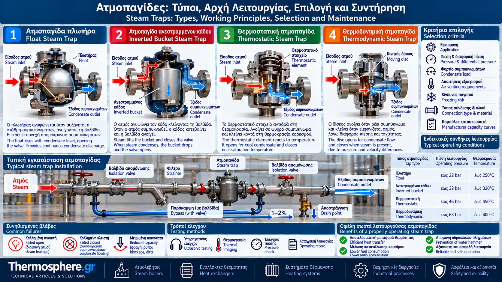
# Steam Traps: Types, Working Principles, Selection and Maintenance
## Introduction
Steam traps are essential components of industrial steam systems. Their primary purpose is to remove condensate and, depending on their design, non-condensable gases while minimizing the loss of live steam.
They are used in distribution networks, heat exchangers, heating coils, process vessels and numerous industrial applications.
Correct selection and maintenance directly affect heat transfer, equipment reliability, energy consumption and operating safety.
A trap that fails closed may cause condensate accumulation, while a trap that fails open can result in continuous steam loss.
## 1. What Is a Steam Trap?
A steam trap is an automatic valve designed to discharge condensate from a steam system without significant live steam loss during normal operation.
Depending on its construction, it may also remove air and other non-condensable gases.
Its operation is based on differences between steam and condensate, including:
- Density.
- Temperature.
- Thermodynamic behavior during flow and expansion.
Not all steam traps use the same operating principle or suit every application.
## 2. Why Must Condensate Be Removed?
When steam transfers heat in a heat exchanger or loses heat through piping, some of it condenses.
If condensate is not removed effectively, it may cause:
- Reduced available heat transfer surface.
- Unstable temperature control.
- Corrosion and localized mechanical stress.
- Water hammer.
- Lower process efficiency.
- Startup problems.
A steam trap is therefore not merely a drain valve but an important component of energy management.
## 3. Three Main Steam Trap Categories
Steam traps are commonly classified as:
1. Mechanical.
2. Thermostatic.
3. Thermodynamic.
Each category uses a different physical property to distinguish the behavior of steam and condensate.
## 4. Mechanical Steam Traps
Mechanical steam traps primarily operate through the density difference between liquid condensate and steam.
### Float Steam Trap
A float trap contains a float that rises as the condensate level increases.
Float movement opens the discharge valve, allowing condensate to leave.
As the level falls, the valve reduces discharge.
Float traps can provide continuous condensate removal and are commonly used in heat exchangers.
### Float and Thermostatic (F&T) Steam Trap
An F&T trap combines:
- A float mechanism for condensate removal.
- A thermostatic air vent for removing air and non-condensable gases.
This is a common option for variable condensate loads and applications requiring effective air venting.
### Inverted Bucket Steam Trap
This design uses an inverted bucket that moves according to the presence of steam and condensate.
When steam enters the bucket, buoyancy increases and the mechanism closes the valve.
When steam condenses or escapes through a designed vent, the bucket drops and the valve opens.
Proper operation requires maintaining the necessary water seal according to the manufacturer's design.
## 5. Thermostatic Steam Traps
Thermostatic traps operate using the temperature difference between saturated steam and condensate cooled below saturation temperature.
### Balanced Pressure Thermostatic Traps
These traps contain a thermostatic element that responds to temperature changes.
When relatively cool condensate is present, the valve can open.
As temperature approaches saturation, the element actuates and restricts flow.
### Bimetallic Steam Traps
Bimetallic traps use elements that deform as temperature changes.
This movement controls valve opening and closing.
Depending on design, they discharge condensate at temperatures below saturation.
Allowing condensate to subcool is not suitable for every application.
## 6. Thermodynamic Steam Traps
Thermodynamic traps commonly use a moving disc.
As hot condensate flows and flash steam forms, changes in pressure and velocity affect the disc position.
The disc closes when the pressure distribution above and below it produces the appropriate resultant force.
As steam in the upper chamber condenses and pressure decreases, the disc can reopen.
Typical characteristics include:
- Compact construction.
- Few moving parts.
- Intermittent discharge.
- Sensitivity to certain low differential pressure or high backpressure conditions, depending on the model.
Selection must follow manufacturer operating limits.
## 7. Comparison of Steam Trap Types
### Float and Thermostatic
Advantages:
- Continuous condensate discharge.
- Good performance under variable loads.
- Effective air venting with the appropriate thermostatic element.
Limitations:
- Proper installation and freeze protection may be required.
- Performance depends on differential pressure.
### Inverted Bucket
Advantages:
- Robust mechanism in suitable applications.
- Operation across a range of pressures within specifications.
Limitations:
- Air venting may be slower.
- Loss of the water seal can affect operation.
### Thermostatic
Advantages:
- Effective startup air removal in suitable models.
- Potential for condensate subcooling.
Limitations:
- Unsuitable where immediate discharge at saturation temperature is essential.
### Thermodynamic Disc
Advantages:
- Compact design.
- Suitable for many steam line drainage applications.
Limitations:
- Intermittent discharge.
- Performance may be affected by backpressure and thermal conditions.
## 8. How to Select a Steam Trap
Selection requires more than choosing the nominal connection size.
Important design data include:
- Application: steam main, heat exchanger or process.
- Maximum operating pressure.
- Minimum available differential pressure.
- Pressure downstream of the trap.
- Normal condensate load.
- Maximum startup load.
- Air venting requirements.
- Freezing risk.
- Condensate return system characteristics.
Required discharge capacity must be checked against manufacturer capacity curves at the worst realistic differential pressure.
## 9. Steam Trap Differential Pressure
Available differential pressure is:
ΔP = Pin − Pout.
Where:
Pin = inlet pressure.
Pout = outlet pressure.
Example:
Inlet pressure: 6 bar(g).
Outlet pressure: 1 bar(g).
ΔP = 5 bar.
Differential pressure directly affects discharge capacity.
Actual operating calculations must account for pipe losses, pressure variations and condensate return backpressure.
Using boiler nominal pressure instead of actual trap inlet pressure can lead to incorrect sizing.
## 10. Sizing Based on Condensate Load
Condensate load depends on thermal duty and operating conditions.
For ideal condensation of dry saturated steam:
ṁcond = Qdot / hfg.
Where:
ṁcond = condensate flow in kg/s.
Qdot = transferred thermal power in kW.
hfg = latent enthalpy in kJ/kg.
Example:
Heat duty: 300 kW.
Illustrative latent enthalpy: 2,100 kJ/kg.
ṁcond = 300 / 2,100 = 0.1429 kg/s.
In hourly units:
0.1429 × 3,600 ≈ 514 kg/h.
Normal condensate load is therefore approximately 514 kg/h.
Final trap selection must use the design load, available differential pressure and manufacturer recommendations.
Startup condensate loads may be significantly higher than normal operating loads.
## 11. Steam Traps and Backpressure
Backpressure is the pressure downstream of the steam trap.
It may result from:
- Condensate header pressure.
- Static elevation.
- Friction losses.
- Flash steam generation.
- Interaction between multiple discharges.
High backpressure may reduce discharge capacity and affect operation of certain trap types.
Not all steam traps can tolerate the same backpressure ratio.
## 12. Proper Installation
Installation must consider:
- Flow direction.
- Permitted mounting orientation.
- Maintenance access.
- Protection against dirt.
- Appropriate isolation.
- Safe condensate discharge or return.
- Water hammer prevention.
A strainer is installed upstream in many applications where recommended by the system design.
Bypass arrangements require strict control because an open bypass can cause substantial live steam loss.
## 13. Common Steam Trap Failures
### Failed Open
Possible consequences:
- Continuous live steam loss.
- Increased fuel consumption.
- Condensate return system overload.
- Increased flash steam generation.
### Failed Closed
Possible consequences:
- Condensate accumulation.
- Reduced heat transfer.
- Unstable temperature.
- Water hammer risk.
### Reduced Discharge Capacity
Possible causes:
- Blocked strainer.
- Dirt in the mechanism.
- Insufficient differential pressure.
- Excessive backpressure.
- Incorrect trap sizing.
## 14. Ultrasonic Testing and Thermography
Steam trap testing can combine:
- Ultrasonic instruments.
- Temperature measurements.
- Thermal imaging.
- Operating cycle monitoring.
- Pressure and differential pressure checks.
Ultrasonic testing can help distinguish normal discharge from continuous flow.
Thermal imaging provides useful information about thermal behavior.
However, a high outlet temperature alone does not prove live steam leakage because hot condensate and flash steam can also produce high temperatures.
Diagnosis must consider trap type and operating conditions.
## 15. Estimating Energy Loss from Steam Leakage
Live steam energy loss can be estimated using:
Eloss = ṁleak × Δh × t.
Where:
Eloss = energy loss in kWh, when flow is expressed in kg/h and enthalpy difference in kWh/kg.
ṁleak = steam leakage rate in kg/h.
Δh = appropriate specific energy difference between steam and makeup water.
t = operating hours.
Example:
Estimated steam leakage: 20 kg/h.
Illustrative specific energy requirement: 0.70 kWh/kg.
Operating time: 8,000 h/year.
Eloss = 20 × 0.70 × 8,000.
Eloss = 112,000 kWh/year.
At an illustrative variable thermal energy cost of €0.06/kWh:
Annual cost ≈ €6,720.
This is an illustrative estimate. Actual leakage and cost depend on system conditions, boiler efficiency and energy prices.
## 16. Inspection and Maintenance Program
An organized program should include:
- A register of all steam traps.
- Identification of trap type and location.
- Recording pressure and application.
- Periodic performance testing.
- Failure documentation.
- Repair prioritization.
- Verification after maintenance.
- Energy savings evaluation.
Inspection frequency depends on application criticality, pressure, operating hours and failure history.
## 17. Maintenance Safety
Steam traps often handle hot condensate and pressurized steam.
Before disassembly:
- Isolate the equipment safely.
- Depressurize the section.
- Confirm the absence of trapped pressure.
- Allow suitable cooling.
- Use protection against burns.
- Follow site safety procedures.
Work must be carried out by appropriately trained personnel.
## Conclusion
Steam traps are critical components for effective condensate removal and minimizing live steam losses.
Selection among mechanical, thermostatic and thermodynamic designs depends on application, condensate load, differential pressure, backpressure and air venting requirements.
Regular inspection, prompt repairs and correct installation contribute to energy efficiency, equipment protection and safe operation of industrial steam systems.
Thermosphere.gr – Technical Knowledge for Professionals.