
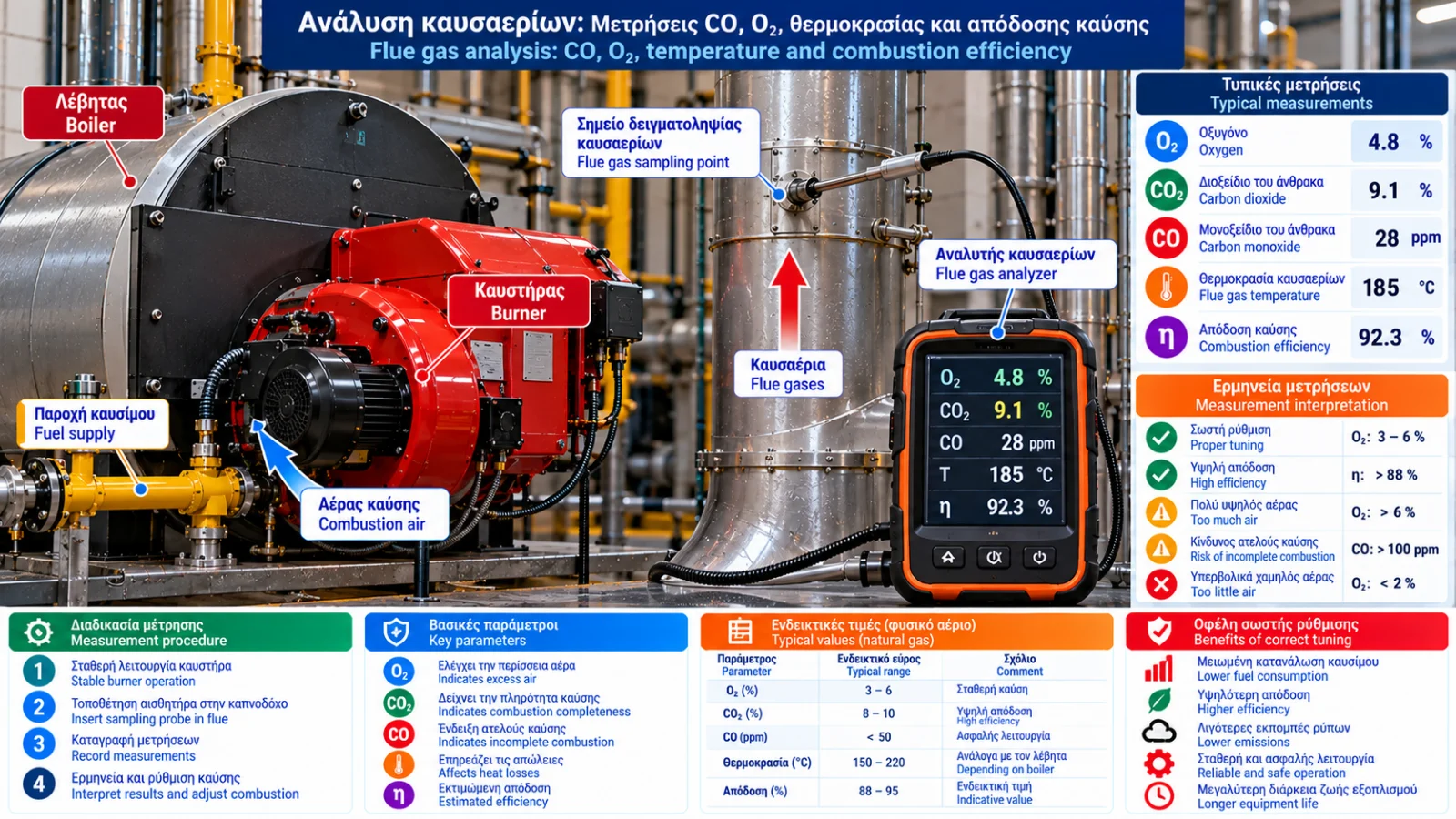
Flue Gas Analysis: CO, O₂, Temperature and Combustion Efficiency Measurements
Flue gas analysis is one of the most important methods for evaluating boiler and burner operation. Suitable measurements can identify incomplete combustion, excessive combustion air, increased heat losses and inefficient operating conditions.
Reliable assessment requires more than one reading. Oxygen (O₂), carbon monoxide (CO), flue gas temperature, combustion air temperature and, where applicable, draught, carbon dioxide (CO₂) and soot measurements must be interpreted together.
Understanding these measurements allows technicians and engineers to evaluate combustion performance and investigate potential causes of energy losses.
1. What Is Flue Gas Analysis?
Flue gas analysis is the measurement of gas composition and relevant physical properties of combustion products.
It is used in:
Oil-fired boilers.
Natural gas boilers.
Industrial burners.
Steam boilers.
Process heaters.
Other suitable thermal systems.
Measurements support maintenance, combustion assessment, fault diagnosis and, when the required method is followed, emissions testing.
2. What Does a Combustion Analyzer Measure?
Depending on its configuration, a portable analyzer may provide:
Parameter | Unit | Purpose |
|---|---|---|
O₂ | % vol | Excess air assessment |
CO | ppm | Incomplete combustion indicator |
Flue gas temperature | °C | Heat loss evaluation |
Combustion air temperature | °C | Temperature difference calculation |
Draught / pressure | Pa or mbar | Exhaust conditions |
CO₂ | % vol | Combustion assessment, measured or calculated |
NOₓ | ppm or mg/Nm³ | Nitrogen oxide emissions, with suitable sensors |
Not all analyzers include the same sensors. Some displayed parameters are calculated rather than directly measured.
3. Oxygen Measurement
Oxygen is a key indicator of the amount of O₂ remaining in flue gases after combustion.
When excess combustion air is supplied, some oxygen remains unused.
Generally:
Higher O₂ may indicate excessive combustion air.
Lower O₂ may indicate reduced air margin.
O₂ changes at constant load may indicate operating or control variations.
However, air leakage into the flue system downstream of the combustion zone can artificially increase measured O₂.
Sampling location is therefore critical.
4. Carbon Monoxide Measurement
CO is a product of incomplete combustion and an important combustion quality and safety indicator.
Elevated CO may be associated with:
Insufficient combustion air.
Poor air–fuel mixing.
Unstable flame.
Inadequate oil atomization.
Burner head problems.
Unfavorable operating conditions.
CO concentration must be assessed according to equipment type, firing rate, manufacturer specifications and applicable requirements.
No single CO limit applies to every combustion application.
Important: Carbon monoxide is toxic. Elevated CO readings require appropriate evaluation and safe corrective action by competent personnel.
5. What Is Undiluted CO?
Some combustion analyzers display a calculated value called CO undiluted or CO air-free.
This expresses the measured CO concentration adjusted to zero residual oxygen.
A commonly used relationship for dry flue gases is:
COair-free = COmeasured × 20.9 / (20.9 − O₂measured)
This calculation is appropriate only when the measurement and reporting bases are compatible.
Air-free CO is not the actual CO concentration at the sampling point.
It should not be confused with emissions corrected to a specified reference oxygen concentration.
6. Understanding CO₂
CO₂ is produced by complete combustion of carbon-containing fuels.
For a given fuel under complete combustion conditions, higher excess air generally produces a lower dry flue gas CO₂ concentration because of dilution.
Many portable analyzers calculate CO₂ from measured O₂ and the selected fuel characteristics.
It is important to determine whether the displayed CO₂ is measured directly or calculated.
7. Flue Gas Temperature Measurement
Flue gas temperature affects sensible heat losses through the stack.
Elevated temperature may be associated with:
Higher burner firing rate.
Fouled heat transfer surfaces.
Reduced heat transfer.
Excess combustion air.
Boiler design characteristics.
Temperatures should be compared under equivalent operating conditions.
For example, comparing readings at 30% and 100% firing rate alone cannot establish whether efficiency has deteriorated.
8. Combustion Air Temperature
Combustion air temperature is required for several stack loss calculations.
Temperature difference is:
ΔT = Tflue gas − Tcombustion air
For example:
Flue gas temperature: 180°C.
Combustion air temperature: 25°C.
Therefore:
ΔT = 155°C
This difference is used with gas composition and fuel properties to estimate flue gas heat losses.
9. How Is Combustion Efficiency Calculated?
Many portable analyzers display calculated combustion efficiency.
In simplified form:
Combustion efficiency ≈ 100% − flue gas losses (%)
The actual calculation method depends on:
Flue gas temperature.
Combustion air temperature.
O₂ or CO₂ concentration.
Fuel thermophysical properties.
Heating value basis.
This calculation does not necessarily include all boiler losses, such as radiation, standby or cycling losses.
Therefore, analyzer efficiency is not necessarily equivalent to overall or seasonal system efficiency.
10. Why Is One Measurement Not Enough?
Combustion performance cannot be established from one oxygen, CO or temperature reading.
For example:
Low O₂ combined with elevated CO may indicate insufficient air or poor mixing.
High O₂ with low CO may indicate acceptable combustion but potentially unnecessary excess air.
Rising flue gas temperature at equivalent load may indicate declining heat transfer.
Unstable readings may indicate combustion instability, changing load or sampling problems.
Measurements must be interpreted together.
11. Where Should the Sampling Probe Be Installed?
The sampling point must be suitable for the equipment and comply with manufacturer instructions and the required measurement method.
The objective is to obtain a representative flue gas sample.
Where possible, avoid:
Locations affected by unwanted air infiltration.
Non-representative flow regions.
Positions where condensate affects sampling.
Locations exceeding instrument operating limits.
The correct sampling location depends on installation geometry and operating conditions.
12. Preparing the Analyzer
Before testing, check:
Instrument condition.
Calibration or scheduled verification status.
Sensor condition.
Sampling filter.
Condensate trap.
Sampling system tightness.
Correct fuel selection.
Battery and pump condition.
Zeroing and preparation must follow the analyzer manufacturer's instructions.
13. When Is a Measurement Reliable?
Measurements should be taken under suitable, representative and sufficiently stable operating conditions.
The required stabilization period varies between burners.
Record:
Burner load.
Fuel type.
Operating temperature.
Sampling conditions.
Measurement time and duration.
For modulating burners, a maximum-load measurement alone does not characterize the entire operating range.
14. Example: Interpreting Measurements
Consider two hypothetical readings from the same natural gas boiler at the same firing rate.
Parameter | Reading A | Reading B |
|---|---|---|
O₂ | 6.5% | 4.2% |
CO | 15 ppm | 20 ppm |
Flue gas temperature | 195°C | 180°C |
Combustion air temperature | 25°C | 25°C |
Reading B shows:
Lower oxygen concentration.
Lower flue gas-to-air temperature difference.
Slightly higher CO.
These changes may indicate lower sensible flue gas losses.
However, they do not prove that Reading B represents acceptable and safe combustion.
Manufacturer requirements, emissions limits, flame stability and operating conditions must also be considered.
15. Identifying Combustion Problems
Combined readings can support initial diagnosis.
Observation | Possible Interpretation |
|---|---|
High O₂ | Excess combustion air or air infiltration |
High CO | Incomplete combustion or mixing problems |
High flue gas temperature | Higher losses or reduced heat transfer |
Variable O₂ at constant load | Control or measurement instability |
Increased soot in oil burners | Atomization or combustion air problem |
Unstable CO readings | Combustion or sampling instability |
These observations are diagnostic indicators, not definitive fault diagnoses.
16. Analysis at Different Burner Loads
For two-stage and modulating burners, combustion should be evaluated at representative firing rates.
Depending on requirements, testing may cover:
Low load.
Intermediate load.
High load.
Load transitions.
Particular attention is needed when steady-state readings appear acceptable but significant deviations occur during load changes.
17. Common Measurement Errors
Common errors include:
Unsuitable sampling point.
Sampling line leakage.
Incorrect fuel selection.
Poor analyzer maintenance.
Sensor problems.
Condensate interference.
Testing before stable operation.
Comparing values with different reference bases.
Measurement reliability should be established before changing burner settings.
18. Example Flue Gas Analysis Report
Parameter | Record |
|---|---|
Date and time | Measurement timestamp |
Equipment | Boiler and burner identification |
Fuel | Fuel type |
Firing rate | % or kW |
O₂ | % vol |
CO | ppm and reference conditions |
CO₂ | % vol, measured or calculated |
Flue gas temperature | °C |
Combustion air temperature | °C |
Draught | Pa or mbar |
Estimated efficiency | % and calculation basis |
Notes | Technical findings |
Maintaining a measurement history supports performance monitoring and identification of gradual deviations.
19. Relevant Technical Standards
Depending on the application, relevant references include:
EN 50379: Specifications for portable electrical apparatus designed to measure combustion flue gas parameters of heating appliances.
EN 676: Automatic forced draught burners for gaseous fuels.
EN 267: Automatic forced draught burners for liquid fuels.
EN 15259: Requirements for measurement sections and sites for stationary source emissions.
EN 14789: Determination of oxygen concentration in stationary source emissions using the specified reference method.
Stationary-source emissions standards do not automatically apply to every portable burner maintenance test. Applicability must be verified.
Conclusion
Flue gas analysis is an essential tool for combustion diagnosis and optimization.
O₂, CO and flue gas temperature should be assessed together using a reliable instrument under documented operating conditions.
The value of combustion analysis lies not only in collecting measurements, but in interpreting them correctly and comparing them with equipment requirements.