
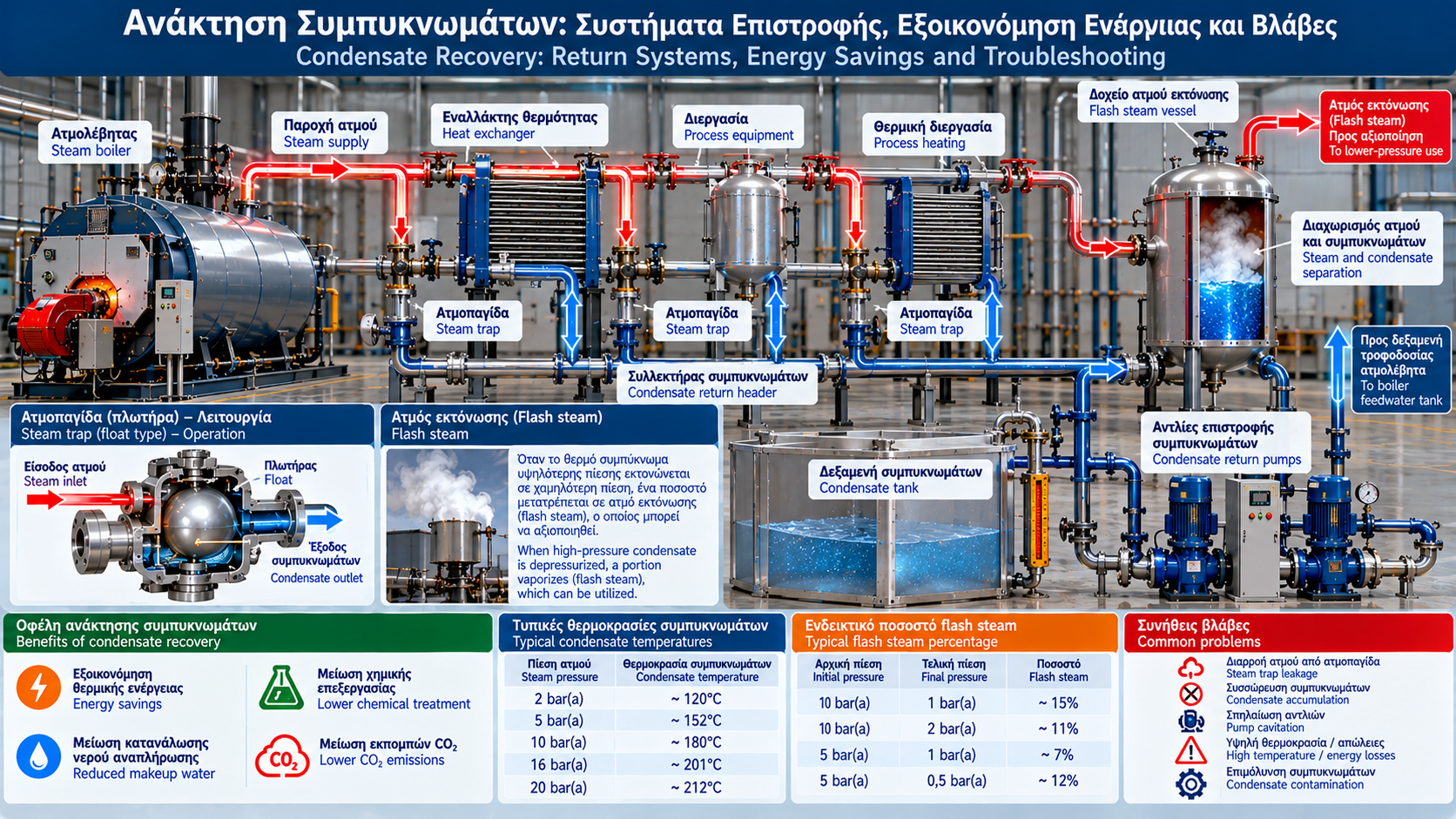
# Condensate Recovery: Return Systems, Energy Savings and Troubleshooting
## Introduction
Condensate recovery is one of the most important opportunities for reducing energy and water consumption in industrial steam systems.
When steam releases its latent heat in a heat exchanger or industrial process, it becomes hot liquid water known as condensate.
Condensate retains substantial sensible heat and, provided it is not contaminated, can be returned to the boiler feedwater system.
Returning condensate reduces makeup water demand, chemical treatment requirements and the energy needed to heat boiler feedwater.
## 1. What Is Steam Condensate?
Condensate is liquid water formed when steam loses heat and changes from vapor to liquid.
In an indirect heating system, steam enters a heat exchanger and condenses while transferring energy to a process fluid.
The resulting condensate may remain at a high temperature and contain substantial recoverable heat.
Its temperature and pressure depend on process operating conditions.
## 2. Why Is Condensate Return Important?
Condensate recovery provides three main benefits.
### Thermal Energy Savings
Hot condensate requires less additional energy to reach boiler feedwater conditions.
### Water Savings
Returning condensate reduces makeup water requirements.
### Reduced Water Treatment Demand
Clean condensate generally contains much lower concentrations of nonvolatile dissolved salts than untreated makeup water.
It may therefore reduce pretreatment load and certain chemical consumption requirements.
However, condensate suitability must always be confirmed through appropriate water quality monitoring.
## 3. Main Components of a Condensate Recovery System
An industrial condensate return system may include:
- Steam traps.
- Condensate collection piping.
- Condensate receivers.
- Return pumps.
- Flash steam recovery vessels.
- Check valves.
- Pressure and temperature instrumentation.
- Level control systems.
- Water quality monitoring.
- Contaminated condensate diversion systems.
Final configuration depends on pressure, temperature, distance and plant layout.
## 4. Open and Closed Condensate Return Systems
### Open Return System
Condensate is collected in a tank vented to the atmosphere.
Advantages:
- Simpler arrangement.
- Easier inspection and level monitoring.
- Generally lower equipment complexity.
Limitations:
- Potential flash steam losses.
- Heat losses.
- Possible oxygen absorption due to contact with air.
### Closed Return System
Condensate returns through a suitably designed pressurized system.
Advantages:
- Potentially improved heat retention.
- Reduced contact with air.
- Opportunities for flash steam recovery.
Limitations:
- More demanding pressure equipment design and overpressure protection.
- Backpressure control requirements.
- Greater system complexity.
A closed return system is not automatically the best solution for every installation.
## 5. Condensate Collection Tanks
Condensate receivers collect returning water before transfer to a feedwater tank or deaerator.
Design considerations include:
- Maximum condensate flow.
- Inlet temperature.
- Required usable storage volume.
- Level fluctuations.
- Venting or operating pressure.
- Overflow protection.
- Inspection access.
- Pump suction conditions.
The tank must be rated for the maximum expected temperature and pressure.
## 6. Condensate Return Pumps
Return pumps transfer condensate to the next stage of the system.
Common options include:
- Electric centrifugal pumps.
- Mechanical condensate pumps.
- Steam-powered or gas-powered pressure pumps.
Selection depends on:
- Flow rate.
- Required head.
- Temperature.
- Available suction pressure.
- Piping configuration.
- Startup and variable-load conditions.
Particular attention must be paid to cavitation risk.
## 7. Condensate Pump Cavitation
Hot condensate is often close to the boiling temperature corresponding to its pressure.
If local pressure at the pump inlet falls below vapor pressure, vapor bubbles can form.
Bubble collapse inside the pump may cause:
- Noise.
- Vibration.
- Reduced flow.
- Impeller damage.
- Unstable operation.
Net positive suction head available (NPSHa) must exceed pump NPSH required (NPSHr), with an appropriate margin according to manufacturer recommendations.
For a simplified open-tank arrangement:
NPSHa = (Psurface,abs − Pvapor)/(ρg) + Hstatic − Hloss.
Where:
Psurface,abs = absolute pressure at the liquid surface.
Pvapor = vapor pressure at liquid temperature.
Hstatic = static liquid height above pump suction.
Hloss = suction line head losses.
## 8. What Is Flash Steam?
When hot condensate at a higher pressure enters a lower-pressure region, some of it may immediately vaporize.
This is called flash steam.
Flash steam is not produced by adding new heat to the system.
It forms because part of the condensate's existing enthalpy is used to vaporize a fraction of its mass.
The amount depends on initial enthalpy and final pressure.
## 9. Flash Steam Fraction Calculation
For saturated liquid undergoing adiabatic throttling, neglecting significant kinetic energy changes:
xflash = (hf,1 − hf,2) / hfg,2.
Where:
xflash = vaporized mass fraction.
hf,1 = initial saturated liquid enthalpy.
hf,2 = saturated liquid enthalpy at lower pressure.
hfg,2 = latent enthalpy at lower pressure.
Example:
Initial condition: saturated condensate at 10 bar(a).
Final pressure: 1 bar(a).
Illustrative enthalpies:
hf,1 ≈ 763 kJ/kg.
hf,2 ≈ 418 kJ/kg.
hfg,2 ≈ 2,258 kJ/kg.
xflash = (763 − 418) / 2,258.
xflash ≈ 0.153 or 15.3%.
Under these idealized conditions, approximately 15.3% of the mass becomes flash steam.
Accurate property values must be obtained from reliable steam tables.
## 10. Flash Steam Recovery
Flash steam may be used in lower-pressure applications when suitable and sufficient demand is available.
A recovery system may include:
- Flash steam separation vessel.
- Low-pressure steam line.
- Pressure control equipment.
- Drainage arrangements.
- Overpressure protection.
- Return of remaining condensate.
Economic performance depends on flash steam availability, operating hours and actual utilization.
## 11. Thermal Energy Savings Calculation
For a preliminary estimate of sensible heat recovered from hot condensate:
Qdot = ṁcond × cp × (Tcond − Tref).
Where:
Qdot = thermal power in kW.
ṁcond = condensate flow in kg/s.
cp = specific heat capacity of water in kJ/(kg·K).
Tcond = condensate return temperature.
Tref = reference makeup water temperature.
This is an approximate calculation for liquid water. Enthalpy balances are preferred for high-pressure conditions or phase changes.
## 12. Practical Energy Savings Example
Consider:
Condensate return flow: 2,000 kg/h.
Condensate temperature: 90°C.
Makeup water temperature: 20°C.
Specific heat capacity: 4.18 kJ/(kg·K).
Temperature difference:
ΔT = 90 − 20 = 70 K.
Recovered thermal power:
Qdot = (2,000 / 3,600) × 4.18 × 70.
Qdot ≈ 162.6 kW.
For 8,000 annual operating hours:
E ≈ 162.6 × 8,000.
E ≈ 1,300,800 kWh/year.
This represents the illustrative thermal energy of returned water relative to water at 20°C.
It is not automatically equivalent to net fuel savings. Actual economic analysis must consider boiler efficiency, system losses, flash steam, deaerator operation and the existing makeup water system.
## 13. Condensate Return Percentage
Condensate return percentage can be estimated as:
R = (ṁreturned / ṁsteam) × 100%.
Where:
ṁreturned = returned condensate mass flow.
ṁsteam = generated steam mass flow.
Example:
Steam generation: 5,000 kg/h.
Condensate return: 3,500 kg/h.
R = 3,500 / 5,000 × 100%.
R = 70%.
Interpretation requires care when direct steam injection, venting, discharge or inventory changes are present.
## 14. Condensate Quality and Contamination
Condensate is not always suitable for direct return.
Potential contamination sources include:
- Heat exchanger leaks.
- Process product ingress.
- Oils.
- Cleaning chemicals.
- Corrosion products.
- Unwanted cross-connections.
Depending on the risks, monitoring may include:
- Conductivity.
- pH.
- Temperature.
- Iron.
- Organic contaminants.
- Process-specific indicators.
Conductivity alone cannot reliably detect every type of contamination.
Critical systems may require appropriate online monitoring and automatic diversion of off-specification condensate.
## 15. Common Condensate Return Problems
### High Vent Temperature and Steam Loss
Possible causes:
- High flash steam generation.
- Live steam leakage through failed steam traps.
- Insufficient flash steam recovery.
### Pump Cavitation
Possible causes:
- High condensate temperature.
- Insufficient static head.
- Excessive suction losses.
- Incorrect pump selection.
### Receiver Overflow
Possible causes:
- Insufficient pump capacity.
- Faulty level sensor.
- Power interruption.
- Blocked discharge line.
### Water Hammer
Possible causes:
- Condensate accumulation.
- Sudden flow changes.
- Inadequate drainage.
- Poor piping geometry.
### Corrosion
Possible causes:
- Oxygen ingress.
- Inappropriate water chemistry.
- Elevated carbon dioxide concentration under certain conditions.
- Condensate contamination.
## 16. Preventive Maintenance Program
Maintenance should include:
- Tank inspections.
- Pump and seal checks.
- Level monitoring.
- Check valve inspection.
- Piping inspection.
- Steam trap testing.
- Insulation inspection.
- Condensate quality monitoring.
- Condensate return percentage tracking.
- Diversion system testing.
- Alarm verification.
Inspection frequency depends on plant criticality, manufacturer recommendations and operating conditions.
## 17. Key Performance Indicators
Useful condensate recovery KPIs include:
- Condensate return percentage (%).
- Return temperature (°C).
- Return mass flow (kg/h).
- Makeup water consumption (m³/day).
- Overall system energy performance.
- Pump failure frequency.
- Number of failed steam traps.
- Discarded condensate volume.
- Water quality indicators.
Trend monitoring supports early detection of performance deterioration.
## 18. Condensate System Safety
Hot condensate may be pressurized and can cause severe burns.
Depressurization of hot water can generate substantial quantities of flash steam.
Essential measures include:
- Properly rated equipment and materials.
- Overpressure protection where required.
- Safe venting.
- Water hammer prevention.
- Isolation and depressurization before maintenance.
- Inspection by appropriately trained personnel.
## Conclusion
Condensate recovery is a fundamental part of industrial steam system energy management.
Returning clean, hot condensate reduces makeup water demand and the thermal energy required for steam generation.
Flash steam utilization, correct pump selection, cavitation prevention and water quality monitoring contribute to reliability and economic performance.
Final evaluation should be based on actual operating data and a complete mass and energy balance.
Thermosphere.gr – Technical Knowledge for Professionals.