
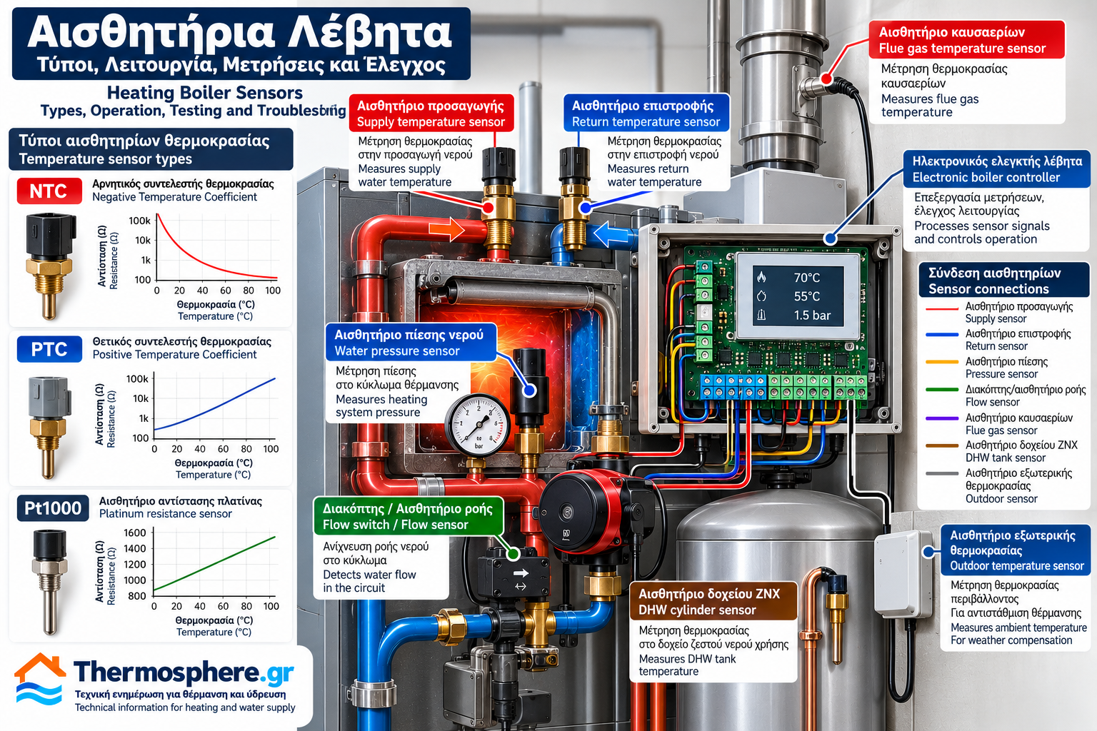
Heating Boiler Sensors: Types, Operation, Testing and Troubleshooting
Sensors are essential components of modern heating boiler control systems. They measure physical parameters such as temperature, pressure and flow, transmitting the corresponding information to the electronic controller.
Using this information, the controller can regulate heating output, manage circulation pumps, control water temperature and identify abnormal operating conditions.
Older conventional boilers often rely on mechanical thermostats for many of these functions. Modern electronic boilers use resistance temperature sensors, electronic pressure transducers and other measuring devices.
Not all boilers incorporate the same sensors. The number, type and position of sensors depend on the boiler design and control architecture.
1. What Is a Boiler Sensor?
A sensor detects a physical parameter and converts it into an electrical signal or a change in an electrical characteristic.
For example, an NTC temperature sensor changes its electrical resistance according to temperature.
The electronic controller measures this resistance and calculates the corresponding temperature using the sensor’s specified characteristics.
A sensor does not necessarily execute an operating command. It provides information that the controller uses to make decisions.
2. Difference Between a Sensor and a Thermostat
A sensor and a thermostat are not always the same component.
Temperature sensor: Provides temperature information to a controller.
Mechanical thermostat: Uses a temperature-sensitive mechanism to change the state of electrical contacts at a specified threshold.
Electronic thermostat or controller: Combines sensor measurements with electronic control logic.
This distinction is important because these devices require different diagnostic methods.
3. NTC Temperature Sensors
NTC stands for Negative Temperature Coefficient.
In an NTC thermistor, electrical resistance decreases as temperature increases.
For example:
At lower temperatures, resistance is higher.
At higher temperatures, resistance is lower.
NTC sensors are widely used in electronic boilers to measure heating water temperatures.
Typical Applications
Depending on the model, they may be installed in:
Heating supply lines.
Heating return lines.
Domestic hot water circuits.
Storage cylinders.
Additional temperature monitoring locations.
Important Technical Note
Not all NTC sensors have the same resistance–temperature curve.
Two sensors with the same nominal resistance at one temperature may behave differently at other temperatures.
Replacement sensors must be compatible with the controller.
4. PTC Temperature Sensors
PTC stands for Positive Temperature Coefficient.
A PTC device generally increases its resistance as temperature rises within its specified operating range.
Some PTC devices are designed for measurement, while others are primarily used for overtemperature protection.
Their resistance characteristics and applications vary by technology.
A PTC sensor cannot be assumed to be interchangeable with an NTC sensor.
5. Pt100 and Pt1000 Sensors
Pt100 and Pt1000 devices are resistance temperature detectors, or RTDs.
They use the temperature-dependent electrical resistance of platinum.
Their nominal resistance at 0°C is:
Pt100: 100 Ω.
Pt1000: 1,000 Ω.
Resistance increases with temperature.
Pt1000 sensors are used in certain heating controllers, weather-compensated systems and industrial applications.
They are not universally fitted to all boilers.
6. Heating Supply Temperature Sensor
The supply temperature sensor measures the temperature of water leaving the boiler.
It is a key control input in many electronic boilers.
The controller may use this measurement for:
Water temperature regulation.
Heating output control.
Operational monitoring.
Detection of abnormal temperature increases.
The sensor may be installed in an immersion pocket or another approved thermal contact position.
7. Heating Return Temperature Sensor
The return temperature sensor measures the temperature of water returning from the heating installation.
This information may be used for:
Monitoring thermal behaviour.
Calculating temperature differential.
Adjusting heating output.
Protecting the heat exchanger.
Improving control performance.
The supply-to-return temperature difference is:
ΔT = T_supply − T_return
For example:
Supply temperature = 70°C
Return temperature = 55°C
ΔT = 15°C
This temperature difference is related to thermal output and water flow rate.
However, temperature difference alone is insufficient to determine the exact flow rate.
8. Boiler Water Pressure Sensor
Some modern boilers incorporate an electronic water pressure sensor.
This device converts water pressure into an electrical signal.
The controller may use this information for:
Displaying system pressure.
Detecting low-pressure conditions.
Activating protective functions.
Generating fault indications.
Other boilers use a pressure switch that changes electrical contact state at a specified pressure threshold.
Pressure Sensor vs Pressure Switch
An electronic pressure sensor provides pressure information.
A pressure switch generally provides a switching signal.
Electronic pressure measurement does not necessarily replace mechanical safety equipment, such as a pressure relief valve.
9. Flow Sensors and Flow Switches
Some boilers incorporate devices that detect water flow.
Depending on the design, these may include:
Flow switches.
Hall-effect sensors combined with suitable flow measurement mechanisms.
Other flow detection technologies.
A flow switch generally confirms that a defined flow condition is present.
A flow sensor may provide a quantitative flow measurement when designed and calibrated for that purpose.
The function depends on the specific hydraulic circuit.
10. Flue Gas Temperature Sensor
Certain modern boilers incorporate flue gas temperature sensors.
These measure temperature at a designated point in the flue system.
The information may be used for:
Thermal monitoring.
Component protection.
Detection of excessive flue gas temperature.
Diagnostic functions.
Not all boilers have a dedicated flue gas temperature sensor.
11. Outdoor Temperature Sensor
An outdoor temperature sensor is used in weather-compensated heating control.
It measures the outside air temperature and provides the information to the heating controller.
The controller can adjust the required supply water temperature according to a heating curve.
For example, as outdoor temperature rises, the required heating supply temperature may decrease.
Weather compensation can improve system operation and reduce unnecessarily high water temperatures.
12. Domestic Hot Water Cylinder Sensor
Heating installations with a separate domestic hot water cylinder may use a cylinder temperature sensor.
The controller uses this measurement to determine when the cylinder requires heating.
Depending on the installation, the controller may activate a cylinder charging pump or operate a diverter valve.
Cylinder temperature management must account for hygiene requirements and scalding protection.
13. Sensor Connections to the Controller
Sensors connect to designated inputs on the electronic controller.
Passive resistance sensors typically use suitable measurement wiring.
Electronic transducers may require a power supply and provide analogue or digital signals.
Terminal assignments, voltages and wiring arrangements vary between manufacturers.
Sensors must not be connected to unidentified terminals without the correct wiring diagram.
14. How Is an NTC Sensor Tested?
The basic diagnostic principle is to compare the sensor’s electrical resistance with the expected resistance at its actual temperature.
Testing must be performed by qualified personnel according to manufacturer instructions.
A typical procedure includes:
Safely isolating the electrical supply.
Identifying the correct sensor.
Disconnecting it according to manufacturer instructions.
Measuring resistance with a suitable instrument.
Measuring or estimating the actual sensor temperature.
Comparing the result with the manufacturer’s resistance–temperature table.
For an NTC sensor, resistance generally decreases as temperature increases.
There is no single universal resistance table for all NTC sensors.
15. Common Sensor Faults
Open Circuit
A broken conductor or internal sensing element can produce an open-circuit condition.
Short Circuit
A fault may cause very low resistance or an incorrect reading, depending on sensor type.
Characteristic Drift
A sensor may deviate from its specified resistance–temperature relationship.
Poor Thermal Contact
Incorrect installation may cause the measured temperature to differ from the actual water temperature.
Wiring Problems
Damaged cables, oxidised contacts and loose terminals may produce intermittent faults.
16. Symptoms of Incorrect Sensor Readings
Depending on the controller, incorrect measurements may cause:
Incorrect temperature display.
Failure to start.
Premature shutdown.
Unstable temperature regulation.
Fault code activation.
Reduced-output operation.
Protective shutdown.
These symptoms do not automatically prove that the sensor itself has failed.
Wiring, controller operation and actual system conditions must also be assessed.
17. Correct Sensor Replacement
Before replacing a sensor, verify:
Exact sensor type.
Resistance–temperature characteristic.
Nominal resistance.
Operating temperature range.
Mechanical dimensions.
Connector type.
Controller compatibility.
Installation requirements.
Two sensors that look identical may not be electrically compatible.
18. Sensors and Boiler Safety
Sensors provide essential operating information to electronic boiler controllers.
However, normal temperature measurement does not necessarily replace an independent high-limit protective device.
Safety functions must be designed and maintained according to the requirements of the specific appliance.
Protective devices must never be bypassed during troubleshooting or operation.
Conclusion
Sensors allow electronic boiler controllers to monitor actual operating conditions.
NTC, PTC and Pt1000 technologies provide temperature measurements, while other devices monitor pressure, flow and additional parameters.
Reliable diagnosis requires an understanding of the sensing principle, electrical characteristics and manufacturer specifications.
Boiler sensors must be selected, tested and replaced according to the requirements of the specific appliance—not merely their appearance or general designation.
This article is intended for technical information. Electrical testing and maintenance must be performed by qualified personnel following appropriate safety procedures.
Thermosphere.gr — Technical information for heating and water supply.