
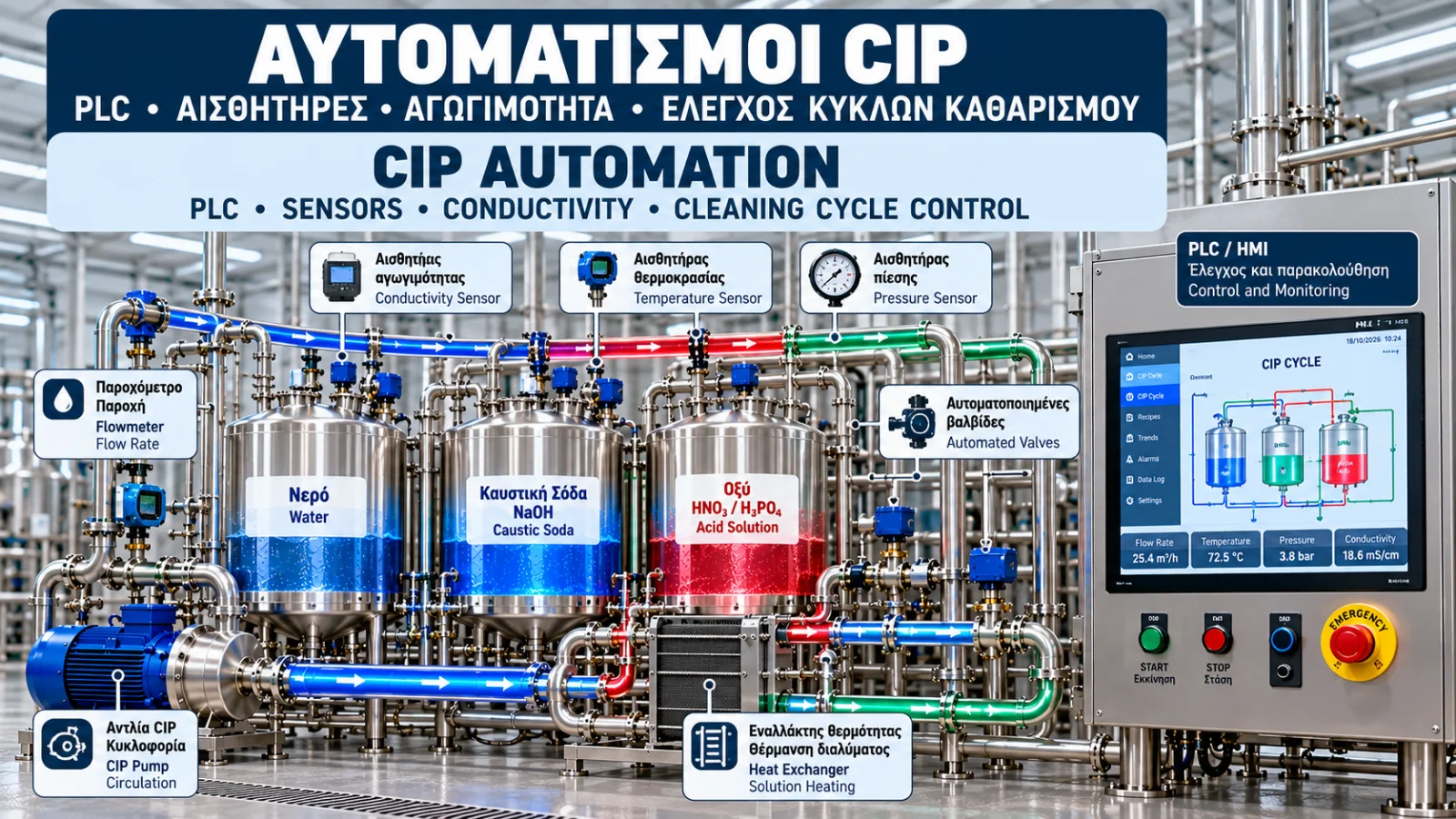
CIP Automation: PLC, Sensors, Conductivity and Cleaning Cycle Control
Introduction
Cleaning in Place (CIP) systems are used to clean appropriately designed industrial equipment without complete disassembly.
Effective cleaning depends on suitable chemical concentration, temperature, flow rate, contact time and complete wetting of the relevant surfaces.
Modern CIP installations use automation systems combining programmable logic controllers (PLCs), sensors, pumps, valves and human–machine interfaces (HMIs).
Automation does not replace hygienic design or cleaning validation. However, it supports repeatable operation, monitoring, traceability and the early detection of process deviations.
1. What Is CIP Automation?
CIP automation is the controlled execution of predefined cleaning sequences.
A typical sequence may include:
System preparation.
Water pre-rinse.
Alkaline cleaning.
Intermediate rinse.
Acid cleaning where required.
Final rinse.
Disinfection where specified.
Cycle completion and recording.
The exact sequence depends on the production process, equipment and validated cleaning procedure.
2. The Role of the PLC
The programmable logic controller is the main controller in many CIP systems.
It receives signals from instruments and sends commands to pumps, valves and heating equipment.
A typical PLC sequence may include:
Confirming that the process circuit is available.
Checking CIP tank level.
Verifying valve positions.
Starting the circulation pump.
Confirming minimum flow.
Heating the cleaning solution.
Starting the cleaning timer when required conditions are achieved.
Advancing to the next stage after predefined criteria are met.
Proper programming, commissioning and testing are essential.
3. HMI: Monitoring and Operator Control
The human–machine interface allows operators to monitor and control the CIP process.
Typical HMI information includes:
Current cleaning stage.
Supply and return temperatures.
Cleaning solution flow rate.
Conductivity.
Tank levels.
Pump and valve status.
Remaining cycle time.
Active alarms.
A critical design principle is distinguishing a command from confirmed equipment operation.
For example, a pump should not be displayed as confirmed running solely because the PLC has issued a start command.
Where required, the actual status should be verified through appropriate feedback signals or process measurements.
4. Conductivity Sensors
Conductivity is one of the most useful measurements in many CIP systems.
It represents a liquid's ability to conduct electricity and depends on the presence of dissolved ions.
Common units include µS/cm and mS/cm.
Conductivity measurements may be used to:
Detect the presence of cleaning solutions.
Identify transitions between water and chemicals.
Estimate chemical concentration using suitable calibration.
Determine rinse completion when the method has been validated.
Conductivity does not directly measure sodium hydroxide or acid concentration.
Its relationship with concentration depends on chemical composition, temperature and other dissolved substances.
5. Temperature Sensors and Heating Control
Temperature sensors monitor cleaning conditions.
Resistance temperature detectors, such as Pt100 sensors, and suitable temperature transmitters are commonly used.
The PLC may control heating through:
Steam control valves.
Hot-water circuits.
Heat exchangers.
Electrical heating systems where installed.
Temperature measurement locations must represent the actual cleaning requirements.
The temperature at the CIP supply outlet may differ from that at the most distant part of the cleaning circuit.
6. Flow Measurement
Flow rate affects the mechanical cleaning action.
Depending on the liquid properties, suitable electromagnetic or other industrial flowmeters may be used.
The PLC can use flow measurements for:
Confirming circulation.
Detecting low-flow conditions.
Protecting the process.
Controlling cleaning-stage timing.
Recording actual cleaning conditions.
In some applications, the cleaning timer may stop accumulating time when flow falls below the required limit.
This behavior must be part of the approved cleaning logic.
7. Pressure Measurement
Pressure transmitters help monitor hydraulic conditions.
Applications include:
Supply pressure monitoring.
Detection of increased hydraulic resistance.
Differential pressure monitoring.
Equipment overpressure protection.
Verification of tank cleaning device operating conditions.
Pressure alone does not prove that sufficient flow or effective cleaning has been achieved.
8. Automated Process Valves
Valves determine the cleaning solution flow path.
Typical equipment may include:
Pneumatically actuated valves.
Position-feedback valves.
Product and cleaning-solution separation valves.
Divert valves.
Double-seat or mixproof valves where required.
The PLC controls valve switching sequences.
In critical applications, correct valve position must be confirmed before starting pumps or introducing chemicals.
9. Interlocks and Operating Protection
Interlocks prevent operation unless specified conditions are met.
Examples include:
Preventing pump startup when tank level is insufficient.
Preventing chemical dosing without a confirmed flow path.
Preventing heating without adequate circulation.
Preventing connections between incompatible chemical circuits.
Preventing production startup before required cleaning checks are completed.
Standard PLC interlocks are not automatically equivalent to independent safety functions.
Where functional safety is required, appropriate risk assessment and safety system design must be applied.
10. Alarms and Fault Management
CIP systems should clearly inform operators when deviations occur.
Typical alarms include:
Low flow rate.
Low or high temperature.
Pressure outside permitted limits.
Low tank level.
Valve position failure.
Conductivity deviation.
Pump fault.
Cleaning-stage timeout.
Each alarm should have a clear cause, priority and expected response.
Depending on severity, the response may involve a warning, timer pause, safe shutdown or cycle cancellation.
11. Example of an Automated CIP Cleaning Stage
Consider an illustrative alkaline cleaning sequence.
Step 1 — Preparation
The PLC verifies tank level, valve positions and pump availability.
Step 2 — Start Circulation
The pump starts, and the system verifies that flow exceeds the required minimum.
Step 3 — Check Concentration
Conductivity is compared with calibrated limits appropriate for the cleaning solution.
Step 4 — Check Temperature
The system waits until the required temperature is reached at the specified measurement point.
Step 5 — Cleaning Timer
Contact time is accumulated according to the approved control logic.
Step 6 — Handle Deviations
If flow, temperature or another critical parameter moves outside its permitted range, the defined response is applied.
Step 7 — Completion
The PLC confirms completion of the stage and stores the relevant process data.
Operating limits are application-specific and must be established through the approved cleaning procedure.
12. Data Logging and Traceability
Recording cleaning data allows each cycle to be reviewed.
Useful records include:
Date and time.
Circuit identification.
Cleaning recipe.
Operator or authorized automatic initiation.
Temperature.
Flow rate.
Conductivity.
Stage duration.
Alarms and deviations.
Final cycle status.
Facilities subject to specific regulatory requirements may also need additional controls for data integrity, access permissions and audit trails.
13. When Is a CIP Cycle Successful?
A “CIP Completed” message should not simply indicate that a timer has finished.
A successful cycle must satisfy predefined, approved criteria.
These may include:
Minimum flow rate.
Acceptable temperature.
Suitable chemical concentration.
Required contact time.
Successful rinsing.
No unresolved critical deviations.
Successful automated execution does not replace cleaning validation or other required cleanliness testing.
14. Optimizing Water, Chemical and Energy Consumption
Automation can help reduce resource consumption through:
Conductivity-based rinse control where validated.
Monitoring actual cycle durations.
Avoiding unnecessary heating.
Early leak detection.
Improved chemical dosing control.
Analysis of recurring alarms.
Resource consumption tracking per cleaning cycle.
Changes to critical cleaning conditions must be assessed and validated where required to maintain cleaning effectiveness.
15. Common CIP Automation Problems
Incorrect Conductivity Measurement
Possible causes include sensor fouling, poor calibration or incorrect temperature compensation.
Cleaning Sequence Does Not Advance
Possible causes include an unsatisfied interlock, insufficient flow or unconfirmed valve position.
Excessively Long Cleaning Cycle
This may result from slow heating, unstable measurements or inappropriate transition thresholds.
Repeated Alarms
Recurring alarms require root-cause analysis rather than repeated resetting.
HMI Status Does Not Match Actual Equipment
Possible causes include faulty feedback signals, communication problems or incorrect display logic.
Conclusion
CIP automation supports repeatability, monitoring and optimization of industrial cleaning.
The PLC executes the sequence, sensors verify operating conditions, pumps and valves perform the required actions, and the HMI provides clear process information to operators.
The greatest benefits are achieved when automation is combined with hygienic equipment design, reliable instrumentation, appropriate deviation management and documented cleaning validation.
Technical References
EHEDG — Hygienic Design Requirements for CIP Installations, Guideline Document 50.
https://www.ehedg.org/3-A Sanitary Standards — Cleanability of Equipment.
https://www.3-a.org/IEC 61131-3 — Programmable Controllers: Programming Languages.
IEC 61511 — Functional Safety: Safety Instrumented Systems for the Process Industry Sector.
ISA-18.2 / IEC 62682 — Management of Alarm Systems for the Process Industries.
ISA-88 / IEC 61512 — Batch Control.
Alfa Laval — Hygienic Fluid Handling and Cleaning Equipment.
https://www.alfalaval.com/