
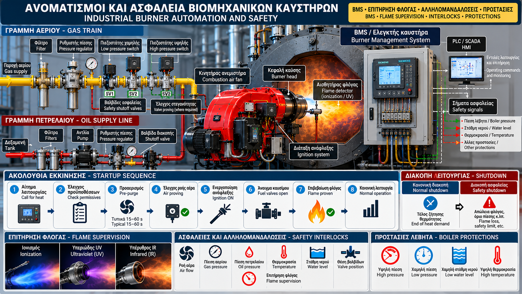
# Industrial Gas and Oil Burner Automation and Safety: BMS, Flame Supervision and Protective Systems
## Introduction
Industrial gas and oil burners operate in facilities where heat generation must be controlled, reliable and safe.
In steam boilers, hot-water boilers, thermal-oil heaters and industrial furnaces, automation is not limited to controlling heat input.
It must also ensure that fuel admission is permitted only when the required safety conditions have been satisfied.
Dedicated burner controllers, Burner Management Systems (BMS), flame detectors, pressure switches, safety shutoff valves and interlocks are used for this purpose.
The exact architecture depends on equipment design, application requirements, risk assessment and applicable standards.
## 1. What Is Industrial Burner Automation?
Burner automation coordinates the functions required for startup, normal combustion and shutdown.
Depending on the design, it controls the combustion-air fan, fuel valves, ignition equipment and firing-rate modulation.
It also monitors specific conditions that must be satisfied before and during combustion.
A START command alone is insufficient to initiate firing if required permissives have not been verified.
## 2. Operating Control Versus Safety Control
Operating control adjusts heat input to match demand.
For example, a steam-pressure controller may increase firing rate when steam pressure decreases.
Safety control has a different purpose: preventing or limiting hazardous conditions.
Loss of flame, failure to confirm a critical condition or activation of a safety limit may require immediate safe shutdown.
These functions can interact, but they must not be confused.
## 3. What Is a Burner Management System?
A BMS manages critical burner safety conditions and sequences.
Depending on the application, it supervises startup permissives, pre-purge, ignition, flame detection and safe fuel shutdown.
Smaller installations may use dedicated certified burner controllers.
Larger facilities may use specifically engineered safety automation systems.
A BMS is not simply another name for an ordinary PLC or SCADA system.
## 4. PLC, HMI and SCADA
A PLC may handle process functions such as heat demand, firing-rate control and signal acquisition.
An HMI allows operators to view operating states, measurements and alarms.
SCADA can provide centralized monitoring, operating history and event logging.
Safety functions require an appropriate architecture and assessment. An ordinary PLC does not automatically provide the required safety integrity.
Likewise, a RUN indication on an HMI does not independently confirm flame presence.
## 5. Startup Permissives
Permissives are signals or conditions that must be satisfied before a particular action is allowed.
They may relate to electrical availability, fan status, fuel pressure, equipment position or boiler conditions.
For example, an active low-water-level protection may prevent startup of a steam-boiler burner.
The complete permissive list is defined by the approved installation design.
## 6. Safety Interlocks
Interlocks prevent or interrupt actions when specified conditions are not satisfied.
An interlock may prohibit fuel admission if the required combustion-air flow has not been proven.
Another may initiate safe shutdown when a pressure or temperature safety limit operates.
Interlocks must be engineered to provide the required safe response, including under foreseeable fault conditions.
They must never be bypassed merely to keep a burner running.
## 7. Burner Startup Sequence
A typical startup sequence may include a call for heat, permissive checks, pre-purge, ignition preparation, controlled fuel admission and flame confirmation.
When the required stages have been completed successfully, the burner transitions to its permitted normal operating state.
Exact timing, damper positions and confirmation requirements depend on the manufacturer and applicable standards.
This description is educational and must not be used as a programming procedure for a specific burner.
## 8. Combustion-Chamber Pre-Purge
Pre-purge is intended to remove potentially flammable residues from the specified combustion space before ignition.
It uses controlled airflow with confirmation of the required conditions.
Purge duration and airflow requirements are not universal.
They depend on system design, volume and applicable requirements.
Bypassing pre-purge can create a serious risk of igniting accumulated fuel.
## 9. Combustion-Air Proving
An electrically running fan does not necessarily deliver the required airflow.
For this reason, suitable pressure- or flow-proving devices are used where required.
Air proving must match the system design and should not rely solely on a fan start command.
Blocked air passages, fan failures or damper malfunctions can affect actual airflow.
## 10. Ignition System
Ignition uses approved equipment such as high-voltage electrodes or a pilot burner, depending on the design.
The BMS manages the sequence and conditions for activation.
Fuel admission is permitted only during specified phases and with the required supervision.
If an acceptable flame is not confirmed within the permitted interval, the specified safe response is required.
## 11. Flame Detection
Flame supervision verifies an acceptable flame signal during the relevant operating phases.
Depending on the application, ionization, ultraviolet or other suitable detection technologies may be used.
The detector must be compatible with the flame type, furnace geometry and burner controller.
The presence of light or heat alone does not establish safe combustion.
## 12. Flame Failure During Operation
Loss of the required flame signal is a critical event.
The safety system must perform the specified fuel shutdown and fault handling.
Possible causes include actual flame loss, sensor problems, wiring faults or combustion instability.
Investigation must be based on recorded information and manufacturer instructions.
Artificially bypassing the flame signal is unacceptable.
## 13. Gas Train
The gas train is an organized assembly of fuel-delivery and safety components.
It may include filters, pressure regulators, pressure switches, automatic safety shutoff valves and valve-tightness testing equipment.
Its configuration depends on capacity, application and relevant requirements.
Safety shutoff valves must be selected and integrated according to the approved design.
## 14. Gas Pressure Switches
Pressure switches monitor gas pressure at defined locations.
Depending on the design, low-pressure and high-pressure protection may be provided.
An abnormal condition may prevent startup or initiate safe shutdown.
Setpoints are not universal across burners.
They must follow equipment specifications and the approved engineering design.
## 15. Gas Safety Shutoff Valves
Automatic safety shutoff valves restrict fuel flow when the system requires a safe condition.
Suitable applications may employ multiple valves and valve-tightness testing arrangements.
Having two valves does not automatically mean every possible failure is covered.
Correct component selection, functional testing and maintenance remain necessary.
## 16. Oil Burner Safety
Oil burner safety requires control of fuel delivery, fuel valves, ignition and flame supervision.
Depending on the technology, fuel pressure, temperature, viscosity or other parameters may be monitored.
Systems using assisted atomization may require additional confirmations.
Inadequate fuel delivery or atomization can cause unstable combustion and protective shutdown.
## 17. Boiler and Burner Protective Functions
A burner is part of a larger thermal installation.
Steam-boiler protection may include high-pressure and low-water-level limits.
Hot-water boilers may require temperature, pressure and other protections depending on the design.
These protective functions must be appropriately integrated into the overall safe shutdown arrangement.
An ordinary temperature-control signal does not replace a required independent safety limit.
## 18. Normal Shutdown Versus Safety Shutdown
Normal shutdown occurs when heat demand ends or an operator issues a permitted stop command.
Safety shutdown is initiated by a specified hazardous or unacceptable condition.
Depending on the event, a latched fault and manual reset may be required.
Reset must not be used to avoid investigating recurring faults.
## 19. Alarm, Fault and Lockout
An alarm indicates a warning or event requiring attention.
A fault identifies a detected abnormal condition or failure.
Lockout is a latched shutdown condition requiring a defined reset procedure before restart.
Terminology and behavior vary by manufacturer.
Accurate diagnosis requires identifying the actual controller code and operating state.
## 20. Example: Burner Does Not Start
Suppose an operator issues a startup command, but the burner remains stopped.
Possible causes include no heat demand, active boiler protection, an unsatisfied permissive or a latched fault.
The first step is to review system indications and event history.
Checks must be performed by authorized personnel without bridging sensors or protective devices.
## 21. Example: Ignition Failure
During ignition failure, the system does not confirm an acceptable flame within the specified period.
Potential causes include fuel-supply problems, ignition faults, flame-supervision issues or unsuitable air conditions.
The controller's exact response depends on its type and approved configuration.
Repeated reset attempts without investigating the cause must be avoided.
## 22. Preventive Safety-System Inspection
Maintenance programs should include the required checks of sensors, pressure switches, valves, wiring, controllers and flame-supervision equipment.
Testing safety functions requires approved procedures, appropriate isolation where necessary and qualified personnel.
Inspection frequency and scope depend on manufacturer guidance, risk assessment and applicable requirements.
Documenting test results supports long-term reliability.
## 23. Conclusion
Automation and safety systems are critical parts of industrial gas and oil burner installations.
The BMS, flame supervision, pressure switches, safety shutoff valves and interlocks work together to ensure that fuel admission occurs only under the required conditions.
Proper engineering, documented operation and periodic verification of protective functions are essential for safe and reliable industrial heat generation.